After the success and launch of the Litl keyboard I wanted to try something a little more mainstream and potentially a little more challenging to design. Most people are familiar with a 65% layout with number keys and an arrow cluster, so that’s what I aimed for here.
As before I wanted to keep similar design constraints to what I had with the Litl keyboard: through hole components only, no complex soldering of USB sockets and great features like OLED and rotary encoders. I also wanted to maintain compatibility with the Pro Micro controller as this was one of the most popular footprints (and has the great combination of being fairly cheap and also updated into RP2040 variants (which would likely be better than the AVR equivalent ones)).
But this caused a slight challenge as the Pro Micro does not have enough pins natively to support a key matrix big enough for a 65% board. It barely had enough for a 40% if you remember from my challenges in the Litl design. This meant that I had to find a new way of fitting more matrix rows or columns onto this controller.
There are a couple ways of doing this. Perhaps the most elegant way might be with a Japanese duplex matrix where you set up 2 keys per (row, column) position and then scan in the row -> column direction and then in the column -> row direction to detect keypresses. This would mean that we could easily fit all the necessary keys onto the controller’s pinout, but we would have to have a custom matrix and also handle the ghosting and additional voltage drop from multiple diodes. I tried out a simple version of this open a breadboard and couldn’t get it work super easily so I didn’t continue much further down this path (though perhaps it might be something fun to follow up on in the future).
My second plan for how to handle this was with a demultiplexer. This is a chip that takes a number (n) of binary inputs and outputs 2 to the n individual outputs. So I could feed it a 4 bit binary value and get 2^4 = 16 outputs out. This means that I could support 16 columns of a keyboard from only 4 pins of a Pro Micro (and also 2^5 = 32 columns from 5 pins too etc.). This would of course require more components to do this (ICs, sockets for the ICs and capacitors for the power rails of the ICs) but I think the enlarged matrix and still relative amount of simplicity was worth it. I would also need a custom matrix scanning code, but this would not be particularly difficult. I got my hands on some demux chips (a pair of 74HC138 ICs) and successfully tested this setup. I think the trickiest thing here was getting my head around the pins used for the demux to determine which demux to turn on or off depending on which half of columns I was scanning at that moment.
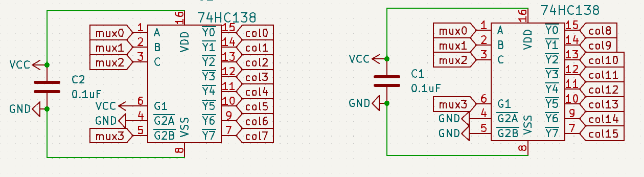
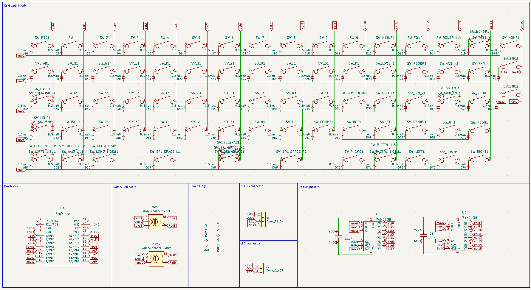
As each of the demuxes that I used were a 3 -> 8 demux I had to use two of them. One for the first 8 cols and another for the last 8. It was a combination of setting G1 high and G2B low for the first 8 cols and vice versa for the second 8 cols that made it work as you can see in the demux pinout below:
Another potential way of doing this would be using a shift register, where the matrix scanning code keeps a handle on the register position and use that to locate where the keypress has been made. I think would have worked fairly easily, but I was super happy with how the demux route went that I stuck with that.
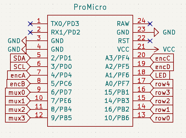
So with this change to a demux for scanning I was able to free up a couple pins on the Pro Micro to be used for other things. I had a total of 5 pins for rows and 4 pins for the demuxes, leaving 9 free pins for other features – much better than what I had on Litl. I ended up using 4 (2 x 2) for rotary encoders and then another 2 for serial comms with the OLED screen. I added an optional header for LED lights under the board too, but that still meant that I had 2 unused pins in the end. Take a look at the ultimate pinout of the Pro Micro below.
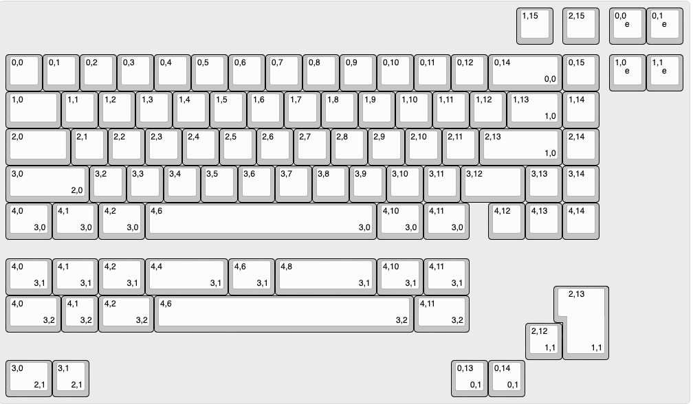
So with the controller and matrix configuration addressed I just needed to come up with a suitable layout and potential options for end builders of the board. 65% layouts are pretty standard so there were not really many surprises here, but I wanted to support most of the usual configurations that people have. These included:
- ISO or ANSI
- Split space (split into 2.25u, 1.25u, 2.75u)
- 7u space (also called Tsangan)
- Split backspace
- Split left shift (technically part of ISO, but you could combine this with the other setups if you wanted)
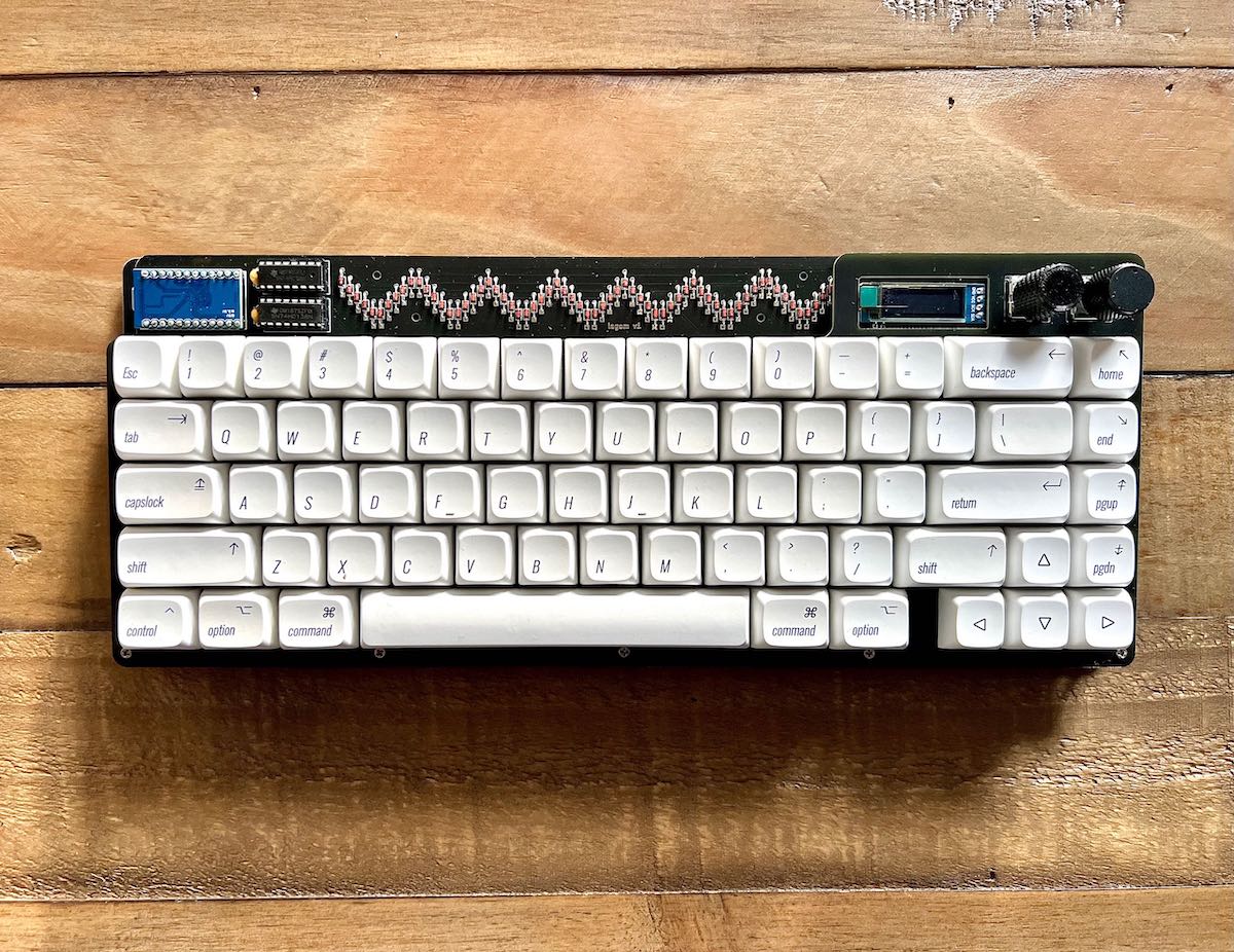
With the extra pinouts that I had on the Pro Micro I could support 2 rotary encoders and an OLED, so that’s what I went for. The ultimate layout of the board ended up like this. You can see alternates by looking at keys with numbers in the bottom right where the numbers correspond to (option, choice).
The next chunk of work was in creating the schematic in KiCad and then the actual PCB layout. I had a little practice from the Litl project, so I was already much faster, but this new board and additional components did come with some added complexity.
I think some of the main things that I’ve learnt with KiCad is to keep schematics as clean and patently obvious as possible. This means using labels where you think they’re necessary and adding notes and graphics to schematics to explain your reasoning where it’s non-obvious. Later down the line future you, or even someone else, might read it and wonder why a specific design choice or a specific component. It’s a lot easier and quicker to add this at the time of creation than try and remember why years later.
In the spirit of keeping the schematic clean I had sections for each different functional part of the board:
Next up was creating the PCB layout. I used similar components to when I built the Litl (with the exception of the couple extra demuxes) so there was little change in the way of new footprints to assign. KiCad makes this pretty easy anyway when you assign footprints to all symbols and then update the PCB from the schematic they are all created (admittedly not in helpful layout). The time consuming part here is in laying out all the switches (and layout variations) correctly and then routing everything in a nice efficient way.
With routing I really wanted to go for some rounded tracks as they look super cool and evoke the style of some retro handmade PCB designs. There are a couple KiCad plugins to enable rounded tracks and auto round tracks and add teardrop style connections. I tried a few different attempts at it (including some routing some tracks in a curved way manually – which you can do out of the box, but it’s a bit of a pain) but in the end I decided it increased the risk for mistakes and also future change and maintenance cost so went without it on the whole.
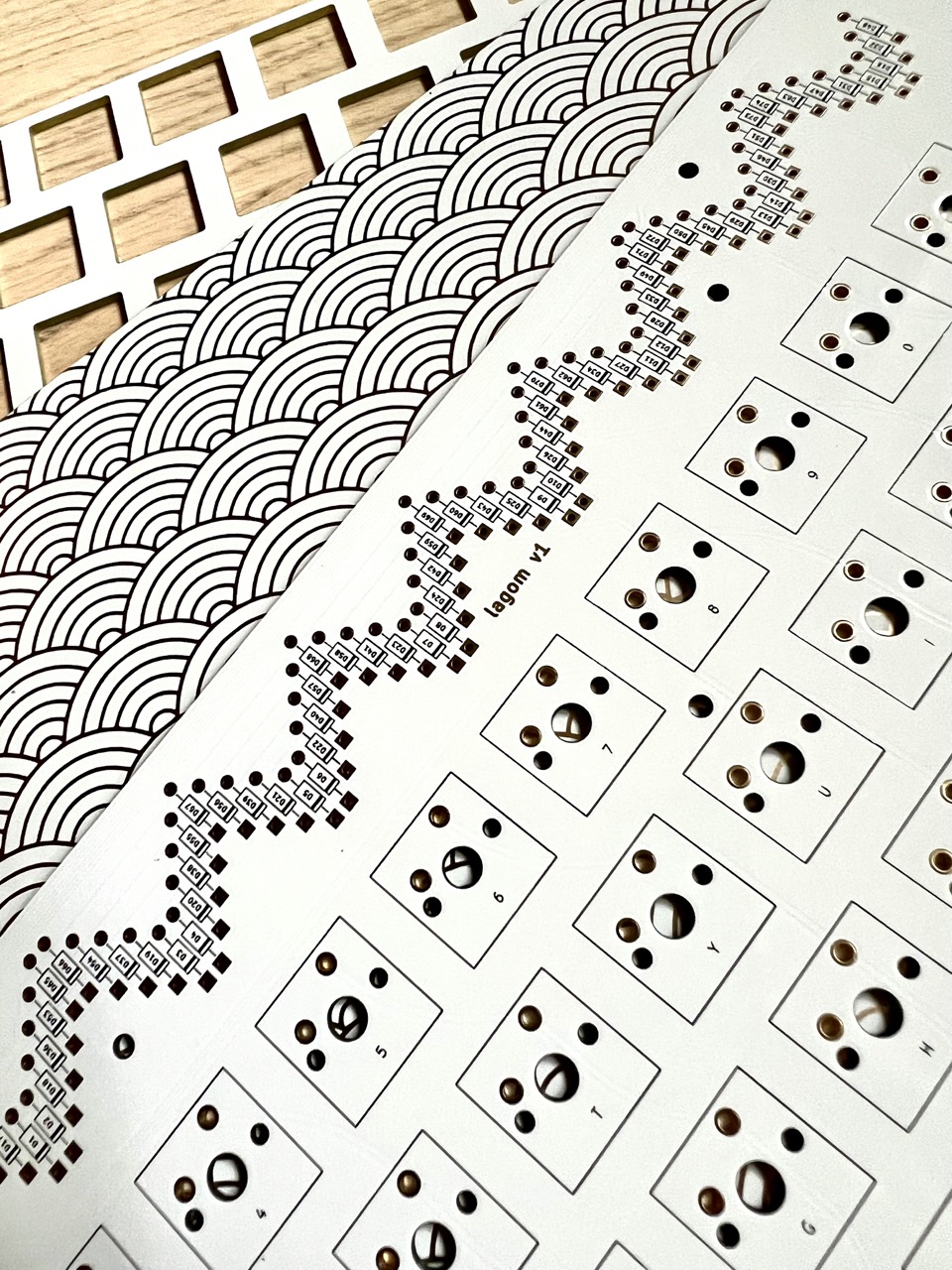
The other part of the PCB design that took a little time was the diode wave. In many other keyboard cases the diodes are a purely functional part that’s hidden in under the keys or hidden in gaps where they’re not at all visible. In the boards that I’ve designed so far I wanted to change this and make them not only visible but a central part of the design. Optimising not only the position with regards to routing but also the overall diode wave took a little focus and concentration, but I think that the final design looks great – especially in person.
Once the PCB was done and double checked a couple times I moved my attention on to the plate and the base, both of which I also designed in KiCad. They’re not strictly necessary, as you could just have the bare PCB and mount to a case (or not…), but I think a base and a plate give a solid enough bare bones ‘case’ and complete the exposed electronics look that I was going for. This took a little more time than with the Litl as there were more keys to lay out and I wanted to make sure that the plate encompassed the OLED and rotary encoders in a cohesive way.
The base also required a little attention too as I wanted to go with another graphic back as I had done with the Litl originally. However this time I wanted to focus more on a simple but elegant geometric pattern – specifically a Seigaiha style pattern evoking simple waves. KiCad is a little tricky when working with graphics, especially if you want to place them on a back layer and especially if you want to tile them, but I got there eventually…
Next was sending off the board for production for a small quantity. There are always things that I end up missing or overlooking when designing and a lot of the time you catch them when you have the board in your hands and can actually see how it is all working. Tools in KiCad like the design rules checker are invaluable, but they can’t tell you if you have the wrong cutout size for a Pro Micro or the screw holes for mounting the case are a couple mm off. As before I used JLC for the boards and ordered 5 in black to begin with.
Not long after they arrived and I was able to start the build process – arguably the most exciting part after designing it in software for so long and not having anything tangible to play with yet. I had sourced some exciting components for the build that I was excited to try – specifically some JWick T1 tactile switches, Glorious Panda Stabilisers and some Retro Mac DSA keycaps. All the other components like the diodes, demuxes, rotary encoders and more I had from previous builds and in stock from Litl.
Luckily during the build process I took lots of photos as I needed them for the build guide that I would eventually need to publish. I won’t go into super amounts of detail here on this, but take a look at the build guide on GitHub or STHLM kb for more.
All in all there were no big issues with the first production run and nothing really needed to be changed – this is always a great surprise when this happens – but it at least means that my ‘go live’ checklist of things to confirm before ordering boards was getting better.
The QMK software was a little different for Lagom due to the custom matrix, but it wasn’t super hard to get working in the end (and you can see the actual code here). I made a Vial version of it too as it’s always much easier and faster to edit your keymap in a visual way (and not everyone who builds one of the boards is happy to dive into QMK right away…).
But I think that’s really all for this project. It was a success! You can see all the related code and files on my GitHub repo and you can purchase kits to build yourself from sthlmkb.com