I kind of made a New Year’s resolution in 2023 to get better, get more familiar with and ultimately relearn electronics, especially analogue electronics. I had done a lot of this before in university, but time spent not using any of these skills, nor thinking about these kind of challenges has a way of making you forget everything. I didn’t really have much of an agenda in doing this either – this was purely for fun, for myself, in a pretty atelic way – a hobby if you will.
When learning this for the first time more than 10 years ago there wasn’t much of a practical vehicle that this was taught with – by this I mean we had the theory thrown at us in lectures and basic labs with minimal practical application and creativity. Likely this was one of the reasons why I didn’t enjoy it as much as I thought I would and why I don’t remember so much of it. I like to learn by doing and problem solving, so the more that I can mould some topic into a challenge or practical project, the more that I will enjoy and retain the knowledge.
So as a vehicle this time I thought synthesisers would be a great choice. I had whet my electronics appetite over the last couple years with some keyboard design, but this was purely digital and I wanted to try a little analogue too for the fun of it – so synths it was.
I think a lot of amazing resources have come out over the last while that make this so easy and enjoyable to learn (even though most of the actual content and circuit designs behind this are not new at all (and probably date from late 60s/early 70s)). Instead of just digging out my old 1st edition copy of the Art of Electronics (which of course I still have around) I used these some of these resources to learn about synthesiser design:
- Make: Analog Synthesizers book by Ray Wilson
- Music From Outer Space (also by Ray Wilson)
- Moritz Klein’s Youtube channel
- Lantertronics Youtube channel – specifically the ECE4450 Analog circuits for Music Synthesis course
- Look Mum No Computer Youtube channel
- Eddy Bergman’s site
- Yusynth
- Why We Bleep Podcast
- Music Thing Modular
- And probably some more that I’m missing right now
It’s so easy to go down a rabbit hole here and start dreaming up, planning and designing super crazy things. But I wanted to keep it relatively chilled at first and work my way up to more complex and more strange things.
My strategy here was to initially lean heavily into the Moritz Klein videos and the excellently detailed PDFs that come with the kits. These give a lot of background to why a certain circuit is built the way that this is and what the intent and tradeoffs are. There’s also a good amount of encouragement to breadboard these ideas (super worthwhile) and final schematics for the circuits.
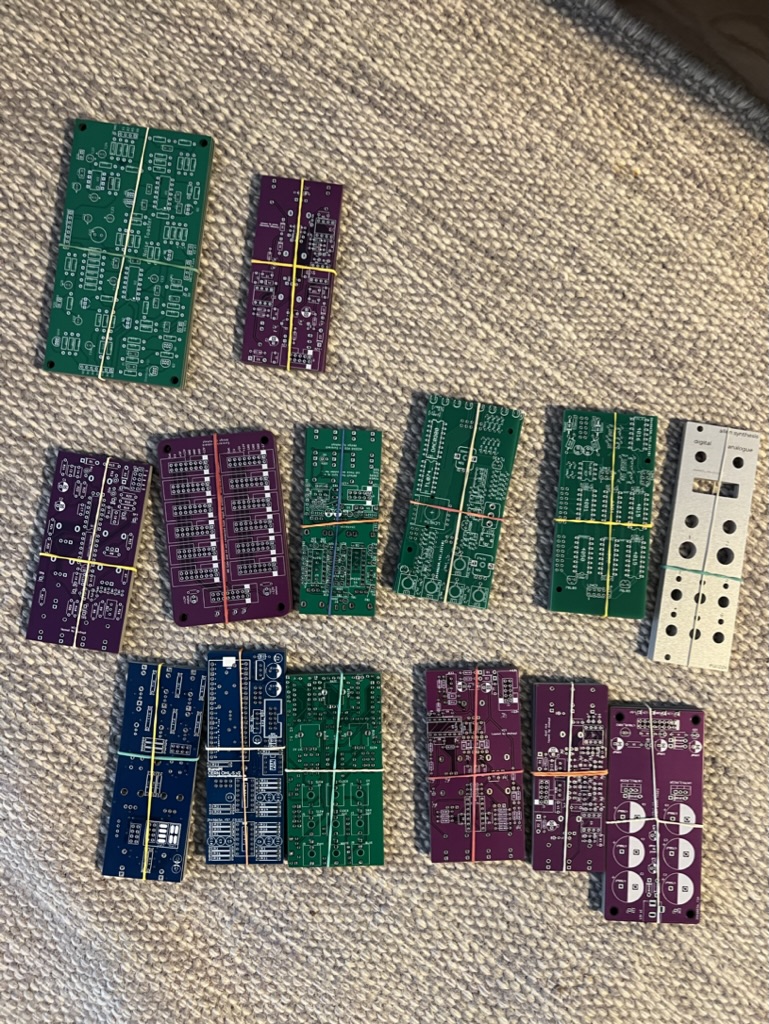
I was able to follow these manuals to recreate the schematics with minor modifications and changes in KiCad, arrange them onto a less than 100 x 100 mm PCB and get them manufactured and shipped from JLCPCB for next to nothing for 5 boards of each.
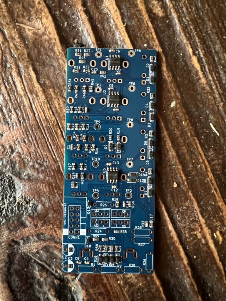
Granted I made some mistakes along the way, but I got a lot faster and more proficient at KiCad, better at understanding component design choices, skilled at sourcing the right components (not always an easy or fun feat) and my attention to detail when studying plans has improved to no end. I’m not sure that I’m up to the level of interpreting some Buchla hand drawn schematics yet, but I’m well on my way. I even (by the end of the year) managed to design a board with SMT components that I got assembled by machine with JLC’s PCBA service.
I will share a little more about the specifics and progress of this over time – but here’s just a little taster of the different boards that I’ve fabricated over the last year.
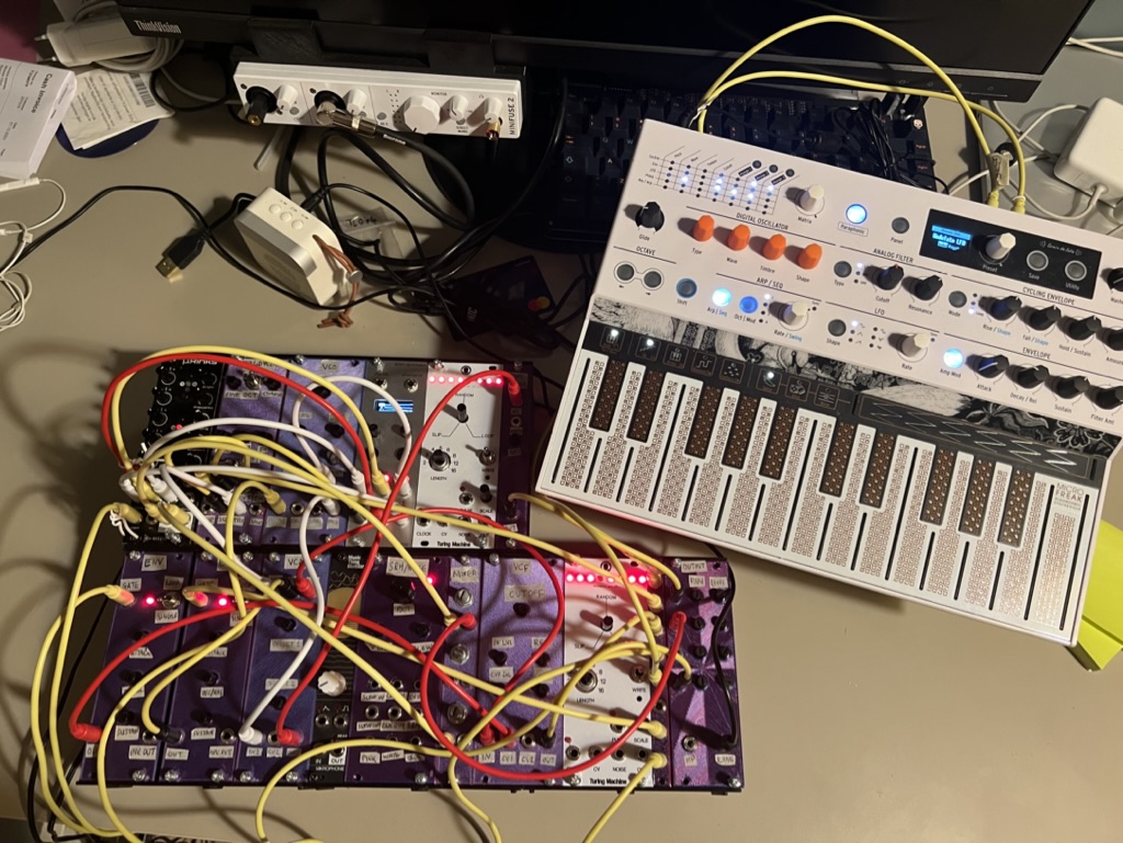
And the system that I have ended up with (for now – it’s always evolving…) is below. Comprising of:
- Arturia Microfreak being used as a CV source
- 3d printed stackable and modular (lol) case
- Mutable Rings clone (the only module that I didn’t build)
- AS3340 self designed VCO
- Moritz Klein VCO
- EuroPi
- Turing Machine
- Wavefolder
- 2 x Env Generators
- Dual VCA
- Mikrophonie v3
- Sample and Hold / Noise
- Mixer
- VCF
- Turing Machine (again)
- Output (mixer)