Ever since I started my foray into mechanical keyboards back in 2020 I was interested by alternative form factors and layout styles. I also wanted to understand what it takes to design, build and program your own board from scratch. So that’s exactly what I did.

TL;DR
If you’re interested in buying a Litl keyboard check out STHLM kb. If you want to see the source code, check out the Litl Github page. If you want to read the story of how it came to be, then read on.
Features
These were the features that I prioritised in the design and why:
- 40% layout (i.e. without the number row) – I wanted something smaller and slightly simpler to design at first. If this was successful then I could move on to larger and more complex boards
- Flexible layout options – Everyone has their preferences with keyboard layouts and if I wanted this board to be used by others I wanted to include a sensible range of layouts (e.g. split space, split backspace, stepped caps)
- Through hole components only – This should be an easy to construct gateway board for people to build and enjoy. If there are complex components to solder, it will increase the difficulty and frustration levels
- Discrete micro controller (Pro Micro or equivalent) – Lots of other through hole kits do not use a discrete micro controller and instead require a separate atmega328 (or similar) chip plus all extras like the USB port to be soldered. While it has a cool aesthetic, soldering some of these parts is hard, and I also didn’t want to lock users into using a specific architecture. This is especially interesting now as there as many new boards starting to use the RP2040 chip instead of Atmel ones.
- OLED and rotary encoder support – I wanted to support these on the board purely because it’s these unique features and input methods that make custom mechanical keyboards so enticing to new users. You generally do not find anything like this on off the shelf keyboards
- Integrated case – After trying a couple boards that had a FR4 (PCB material) sandwich style case, I realised that this was a simple and elegant way to build a board. It’s fairly cheap to manufacture, easy to build and looks and feels great.
- Well supported firmware – The board should use standards like QMK and Via or Vial to enable maximum compatibility and easy of setup and customisation for end users.
Layout
The first step to designing was to settle on the layout. Keyboard layout editor is a great tool for this as it enables you to easily customise and try different layouts to see if they could work. It also comes in helpful later when you have to create the firmware and you need to generate the key matrix. Getting it right at this point is key as making changes to the layout and arrangement later involves a lot more work (especially if you’ve laid all the traces in KiCad).

The layout that I settled on in the end looks was this one. You can see the optional layouts here too, and KLE also gives you the ability to link to the exact layouts like this.
Making the schematic
Now that the layout was sorted I was able to move onto the PCB design. I did this with KiCad. It’s a great piece of open source software with not too steep of a learning curve (though it has its quirks). There are a lot of great tutorials out there to learn it, and I quickly picked up the ropes.
The first step involved designing the schematic for the board. This meant laying out the matrix from earlier and determining how all the rows, columns and additional things on the board would connect to the micro controller. I used a couple of great keyboard specific libraries for the symbols and footprints here.

I also started to understand another challenge when it comes to designing keyboards. How do you maximise the keys that you can have for a given pin count on the controller. With my layout I had 4 rows and 12 columns, and if I connected that in a simple fashion would mean that it used 4 + 12 = 16 pins on the controller. This would be pretty much all of them on the Pro Micro and wouldn’t allow space for OLEDs or rotary encoders, so I had to do a different sort of matrix to make this work.
As the most efficient matrix is a square, my strategy was to make my layout more square like. So I doubled up the columns and essentially created a 8 row by 6 column board (= 14 pins!). I didn’t realise it at the time, but I after reading a little about keyboard matrix design here, I had made a type of duplex matrix.
PCB Layout
Now that I had a schematic down for the board I had to convert this into an actual PCB layout that I could get fabricated. This involved assigning footprints to all of the symbols and components that I had on the schematic. Luckily there are some great libraries with pre made keyboard footprints in the common MX style. These proved invaluable when laying out the board. Another tip that was helpful was setting the grid size of Kicad to a multiple of the key switch dimension (19.05 mm) so then positioning of switches became far easier now that they snapped to a grid.

As I had spent time carefully assigning the correct size value to each switch earlier (i.e. 1u or 1.25u or 1.5u) it was fairly straightforward to lay out all the switches in the correct fashion. Once that was done I was able to place the micro controller footprint and the rotary encoders and OLED. I really liked the aesthetic of exposed and patterned diodes so I spent some time painstakingly placing diodes in a repeating fashion (that also minimised trace lengths). It took some time but was well worth it for the finished product.
Then I had to spend some time focussing on laying the traces that connect the different nets or connections of the PCB. This was probably the most time consuming part, but one you get into it, it’s rather rhythmic and enjoyable. After running a couple electric and design checks I was mostly done with the PCB.
Plate and base
I wanted to have a simple sandwich style case where the PCB was essentially floating in-between a plate and a base and only connected via the switches soldered to it. In order to do this I needed to create a plate and a base that were slightly larger and had matching screw holes so they would all fit correctly.
I initially designed the outline for these in the same Kicad file as the PCB so that the holes would be aligned. I then jumped over to keeb.io’s plate generator (and again used the output from KLE) to generate the correct plate size and cutouts. This I imported to Kicad to double check and then created a separate Kicad project for the plate with the correct holes and dimensions. Creating the base was much easier as it was essentially the same as the plate minus the holes but with some additional graphics on the back.
Manufacturing
That was most of the design done. And now it was time to hope that I got it right and order some prototypes to see how they looked and worked. As always JLCPCB turned out to be a great vendor to order this from (especially with their rapid turnaround) and in no time I had a some boards physically in my hands and ready to build.
Construction
I preempted the arrival of the board by stocking up on some switches (I used Gateron Pro Milky Yellows), some stabilisers (I got some cheap KBDfans branded ones), a Pro Micro and a bunch of diodes and other components. So once the boards arrived I was ready to get building!
First step was soldering the diodes. I 3D printed a little diode bender that helped a lot with getting the right diode bend for all 47 of the diodes on the board. But soon enough they were done. Then came the Pro Micro. I had used a footprint on the board with slightly zigzag holes so that potentially you could get away with not soldering the controller directly onto the PCB and let it fit with friction. I tried it this way initially and it didn’t really connect so well, so I opted for soldering in the end.
Now I had the most basic selection of parts connected to the board, I could begin testing to see if the matrix and keyboard actually worked. But in order to do this I had to flash working firmware to the Pro Micro
Firmware
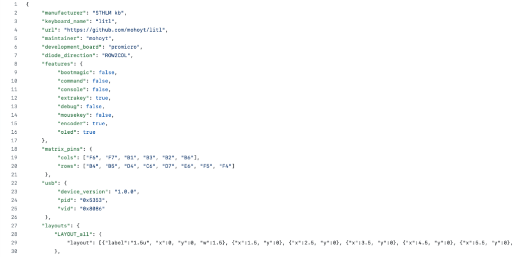
This involved making the firmware to begin with. As with a lot of of custom keyboards (including the ones that I had built earlier) I opted to go with QMK due to its ubiquity and fairly decent ease of use. There are also great forks of the QMK project like vial-qmk that allow real time configuration that I could leverage later on if I wanted to.
The trickiest part was getting the matrix laid out correctly. This was probably made slightly harder due to the duplex style matrix that I had gone with to make the best use of the pinouts. But after some careful checking of the Kicad schematic I figured it out. You can see the QMK firmware that I used here.
And after configuring the rest of the things that I needed for a basic but working keyboard, and looking at a lot of examples, I had something that compiled successfully that I could flash to the Pro Micro controller using QMK Toolbox.
Construction (continued)
Now that I had a partially built board and working firmware I was able to connect the board to my computer via USB and see what worked and what didn’t. My way of testing this was to open a text document and then go from one keyswitch footprint to another (remember there are no switches soldered on just yet) and check that when I shorted the contacts together with tweezers I got a letter, and hopefully the correct letter, appearing on screen.
And… it didn’t work. I got nothing at all. Super confused at first I took out the multimeter and spent some time checking out the continuity of the pins and traces and all looked good. But then towards the end of checking that I realised that the diode footprints that I was using had been reversed at some point during the Kicad stage, so I had all the diodes backwards (even though they looked completely correct from the silkscreen on the PCB).
But not a problem! All I had to do was change the code in the firmware from a COL2ROW matrix to a ROW2COL matrix to indicate the different type of polling that the controller now had to do. After re-flashing the Pro Micro and trying again with tweezers on the switches, key presses started magically working. There were a couple keys that didn’t work so well, but upon closer inspection of the diodes I realised that I had some cold solder joints that needed a little love.
As everything was working as expected I unplugged the controller and started finishing the building of the board. I attached the stabilisers, lubed them as much as I thought necessary and started soldering in the switches everywhere.
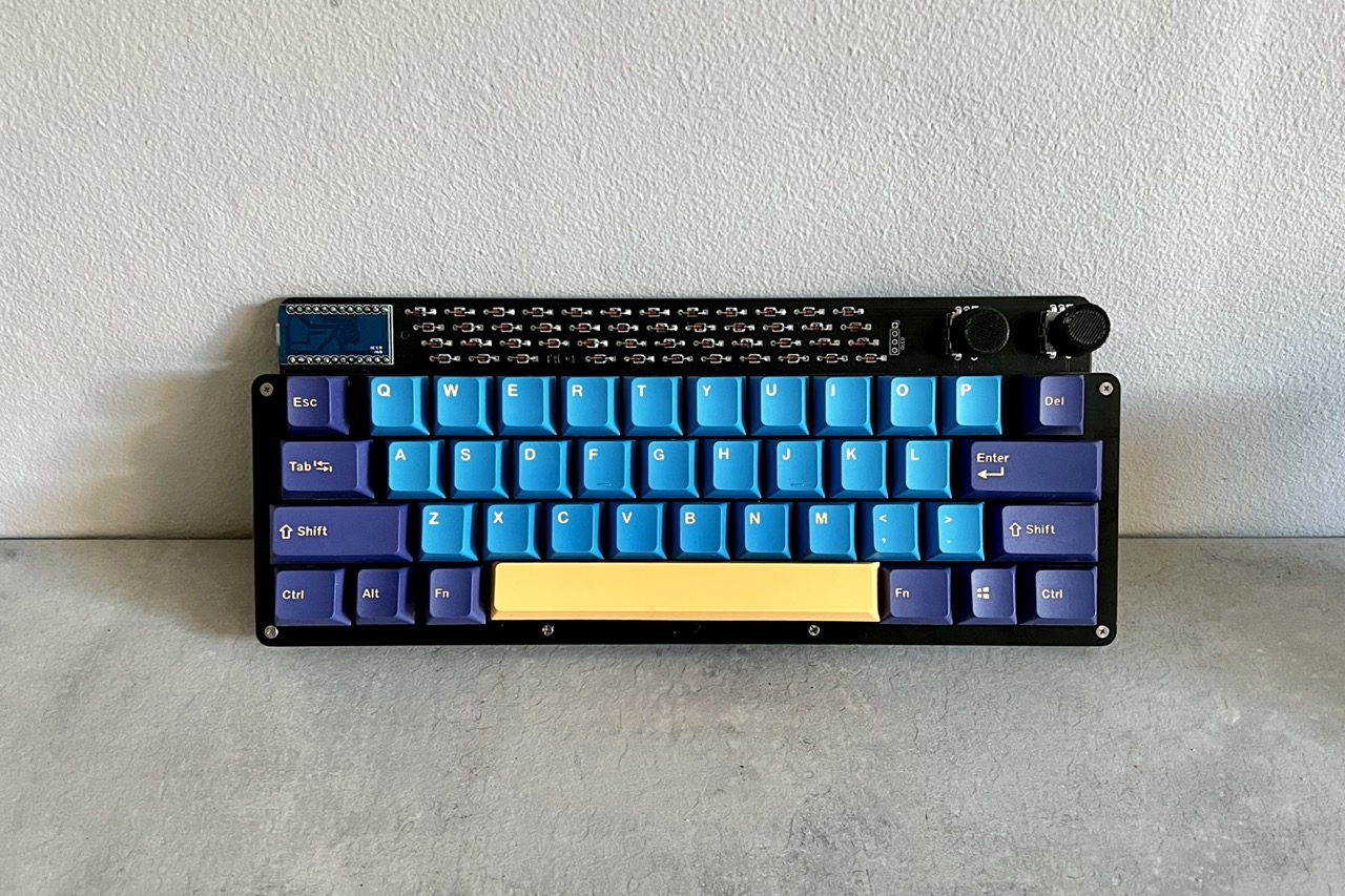
I decided to go for a split space layout as I thought that the additional space could be useful as a modifier for numbers or arrows (as this layout lacked that). The PCB layout that I had ultimately went for supported either 2 rotary encoders or 1 rotary encoder and 1 OLED screen. This was because I had a very limited number of pins on the Pro Micro to use, but I left the ultimate choice up to the end user building the board.
In my case I went for one rotary encoder and one OLED so that I could test that both worked fine. After completing the build and assembling the case with M2 screws and standoffs around the edge, the board was done. I added some retro Apple-esque keycaps I had bought from AliExpress and I was ready for more testing.
Luckily now every key worked as expected and I was able to start using the keyboard to edit and improve its own firmware. I wanted to put something fun on the OLED screen and after playing around with a couple examples I settled on a WPM HUD (like in the image above) that tracks and graphs your WPM over time and a Bongocat, which is exactly what it sounds like: a cat playing bongos in time with your typing.

I also managed to get Vial working with the board so this meant that I could configure the board on the fly with the Vial app or web tool. I made a couple pre-compiled firmware files with the different OLED animations and Vial to make it easier for users to install them. They’re available here on Github.
Lessons learned from v1
All in all the first version of the board went pretty well. I was able to use it for work without any serious issues (besides getting used to a 40% layout without a number row), but there were a few quirks that I noticed that I realised I needed to sort out before making a future version. These issues ended up being missing holes for a 5 pin key switch on one key, accidentally reversing the OLED mounting pins (so the OLED had to be mounted over some of the diodes rather than over the spare rotary encoder hole) and routing some traces under the ‘litl v1’ name in the diodes so that it was less clear. But these were all fairly trivial to solve and are now included in the latest version of the board (v2).
Finalising and launch
So that’s about it for this project.
If you want to see the files used to design and build and power the Litl keyboard, they are all available on my Github.
If you’re interested in purchasing a Litl keyboard for yourself, I sell DIY kits with most of the components that you need on STHLM kb.
Happy typing!
Someone is selling your keyboards.
https://www.tokopedia.com/ncoshop/lagom-dan-litl-pcb-mechanical-keyboard-litl-pcb-bb410?extParam=ivf%3Dfalse%26src%3Dsearch
https://www.tokopedia.com/hadi-syafiq/lagom-65-mechanical-keyboard-pro-micro-oled-throughhole-pcb-custom?extParam=ivf%3Dfalse%26src%3Dsearch
https://www.tokopedia.com/jstoreit/case-akrilik-lagom-by-mohoyt-custom-diy-mechanical-keyboard?extParam=ivf%3Dfalse%26src%3Dsearch
is this allowed?
Thanks for the heads up! Will take a look into this. It’s not allowed based on the terms of the license.