I want to understand more about synthesisers and analogue electronics. Yes, technically I had studied a lot of it at university but I had also forgotten much of it, and when studying it then it wasn’t perhaps as practical and hands on as I wanted it to be.
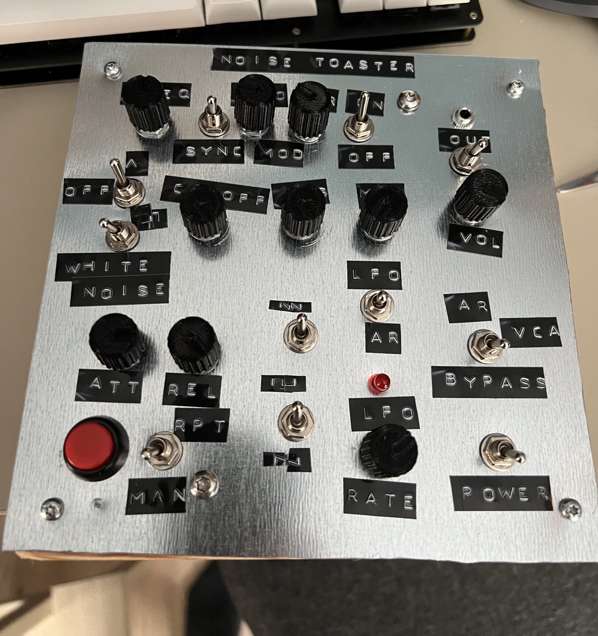
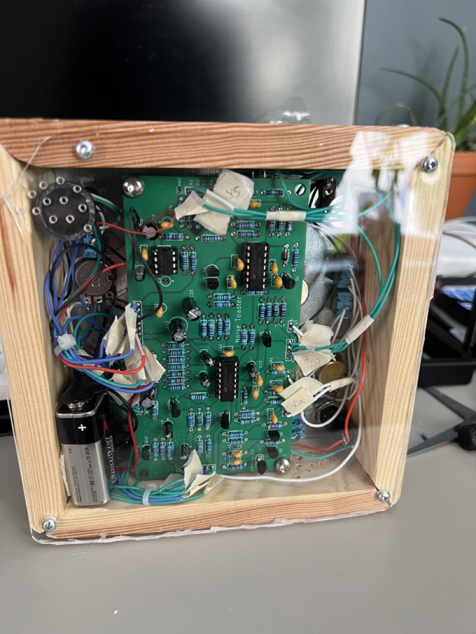
A way of doing this was to do some hands on DIY and build some things myself. I started with sourcing and building a MFOS Noise Toaster – essentially a lo-fi noise box with the basic building blocks of a monophonic synthesiser in it (an oscillator, LFO, filter, AR envelope etc).
But I really liked the Moritz Klein Youtube series where he was explaining how individual parts of a Eurorack work and build modules from scratch on breadboards. There’s also a great line of kits in collaboration with Erica Synths where you can build and learn about these.
I want to use this as the basis of learning more and hopefully be able to follow along with the videos and the PDFs that are included when purchasing the kits (but are conveniently also available online). These PDFs are great learning resources.
I had a large amount of the components already at home that I could use to start building on breadboards, so I only had to order a few extra things from Tayda and AliExpress. But after reading some of the PDFs, he suggested using 2 9V batteries to create a dual 9V supply in an easy and fairly safe way (albeit not at the typical dual 12V used in Eurorack systems). I wanted something that I could potentially use for the breadboarding and also in a finished product, so I didn’t really feel like using the 9V battery solution (and also parts are so cheap that it would probably pay for itself after a couple rounds of 9V batteries).
So I needed a dual (plus and minus rail) 12V power supply. This I could of course buy in completed form, or in kit form, but what was the fun in that (less learning there). So I decided to take inspiration from a couple designs out there and layout and fabricate my own dual 12V power supply that I could use.
The main influences that I took for this were the MFOS wall wart power supply, the power supply from AI Synthesis and the Frequency Central supply (which is where I got the layout from). I know what you’re thinking here: it’s pretty dangerous playing with mains level electricity, and I agree. But the great thing about these designs was that they take input from a 12V AC wall wart transformer. So I’m not dealing with 240V circuitry, but only 12V, reducing the risk somewhat.
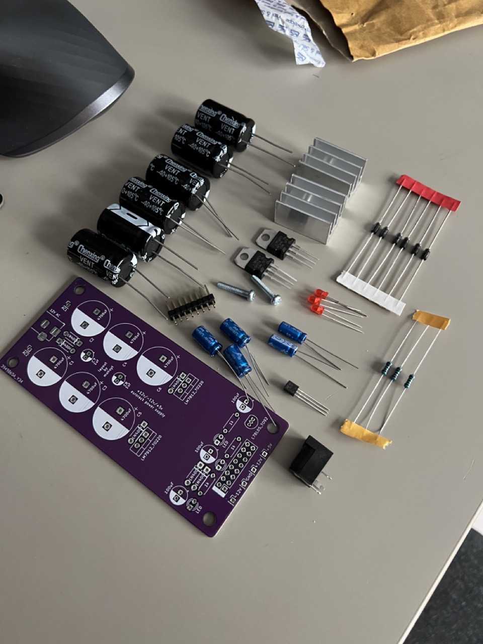
Anyway I put my PCB design stills to work and came up with a PCB based on a couple of the influences above. Wonderfully it’s not a big PCB (under the 100mm x 100mm JLCPCB cutoff) so the fabrication was very cheap. And about a week or so later I had the boards in my hands and ready to go.

Next up was building the boards. I had a bunch of relevant parts though I had to order a couple more capacitors that were big enough (4700uF!) – but for me the soldering and building is one of the best parts. Seeing your vision and design coming to life!
Not the hardest build to do either tbh. Everything was on one side and fairly well spaced, so it was really a matter of putting things on in height order so that it made soldering easier. Not long after I was done!
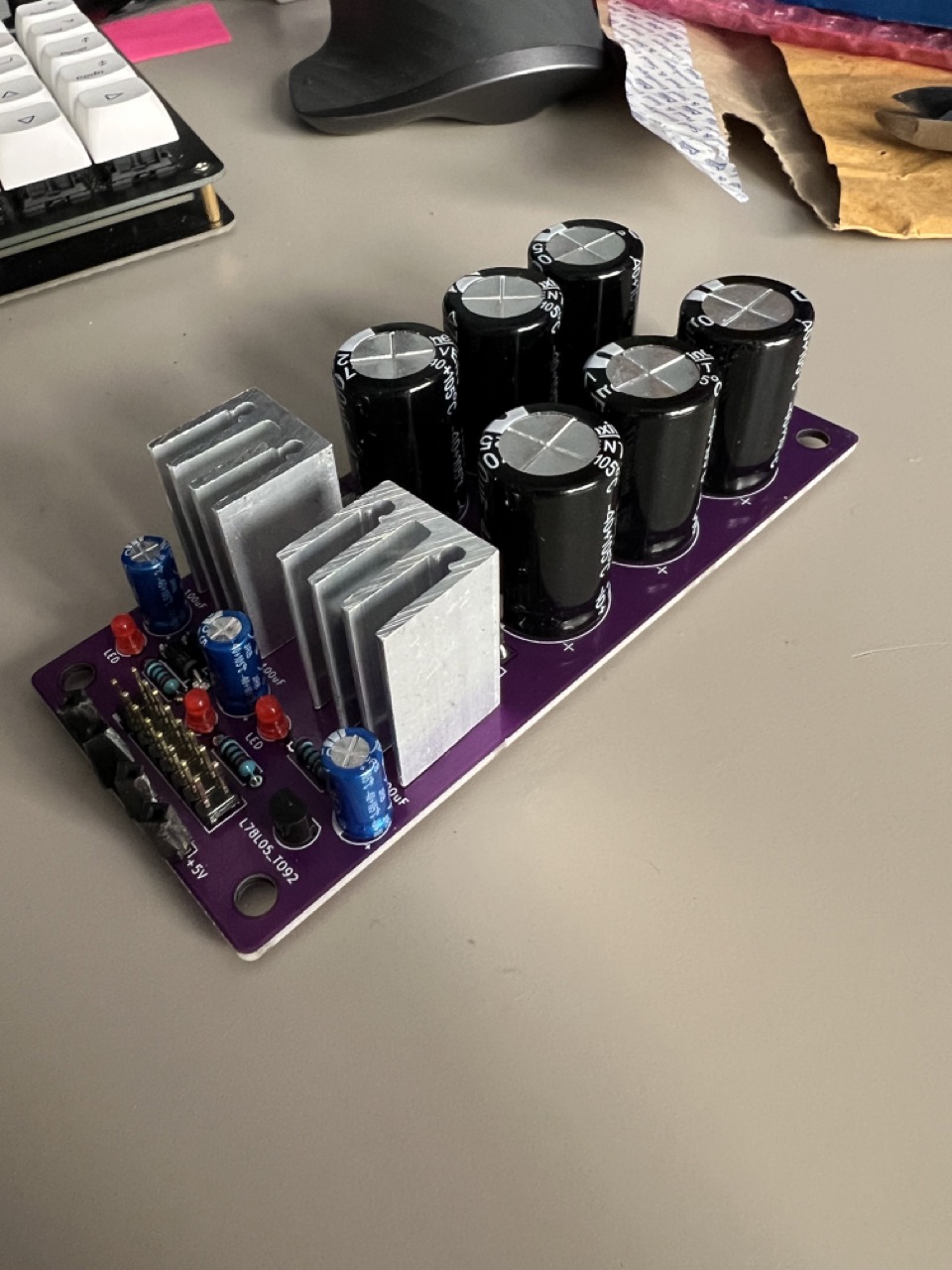
And now ready to test! I had a quick continuity test with a multimeter with the device off to make sure that components that should be connected were connected as expected and I then I plugged it in to see if anything blew up (thankfully no!), the LEDs went on (thankfully yes!) and the power at the output was correct (also thankfully yes!).
Now that this was done I can power my breadboard projects and future eurorack projects more easily and reliably! On to the next project!
Improvements for next time
As with all projects that you do there are a couple issues that you spot a little later on, sometimes in the assembly phase and other times after months or even years of use. For this project there were a couple things that I could have improved upon that I will bake into a v2 PCB if I ever get some manufactured. These were:
- I didn’t allow space or the correct footprint for the polarised 16 pin Eurorack style power header. This is a (fairly common?) format that ensures that power cable can only be connected the correct way around and prevents modules from being damaged. I would need just a little more spacing around the connector to allow for this so not a big change to make.
- The second improvement is again to do with the power connector. I designed the PSU with a +5V out too, so I needed to use a 16 pin connector instead of the 10 pin connector that you see sometimes. In addition to the 5V pins there are also Gate and CV pins on the connector that allow Gate and CV signals to be passed through the bus (as a potential default/unplugged or normalised behaviour) rather than relying only on patching. This is a neat feature that I haven’t seen a huge number of modules use (but I’m pretty new to all this so what do I know!). But anyway, getting to the issue at hand here, I hadn’t appreciated how I should handle these so I just connected them to ground, thereby making them potentially useless if a bus board also connects to these nets and there are modules that want to use these features.
- I kind of worked around this a little bit in the bus board PCB that I made next in that I created a specific connector that on board for the PSU IN connector that didn’t have a connection on these 2 nets, but all the other connectors on the board had these 2 nets connected correctly. So if you use both my PSU and the expander then you should be good to go.