
Background
I saw some really neat well designed 3d printed keyboard cases recently at an event that I went to. These cases were not the typical boxy tray-like monstrosities that you see all over the place, but instead they were intricate multi-part, somewhat organic looking and really nicely finished. Unlike most of my previous 3d printed models, the builders of these cases had gone to the effort of sanding, filling, priming and painting the finished product – and it looked so much better. This gave me inspiration to try this myself. I always knew that you could post process 3d printed models, but had never really gave it a good go. So here was an opportunity.
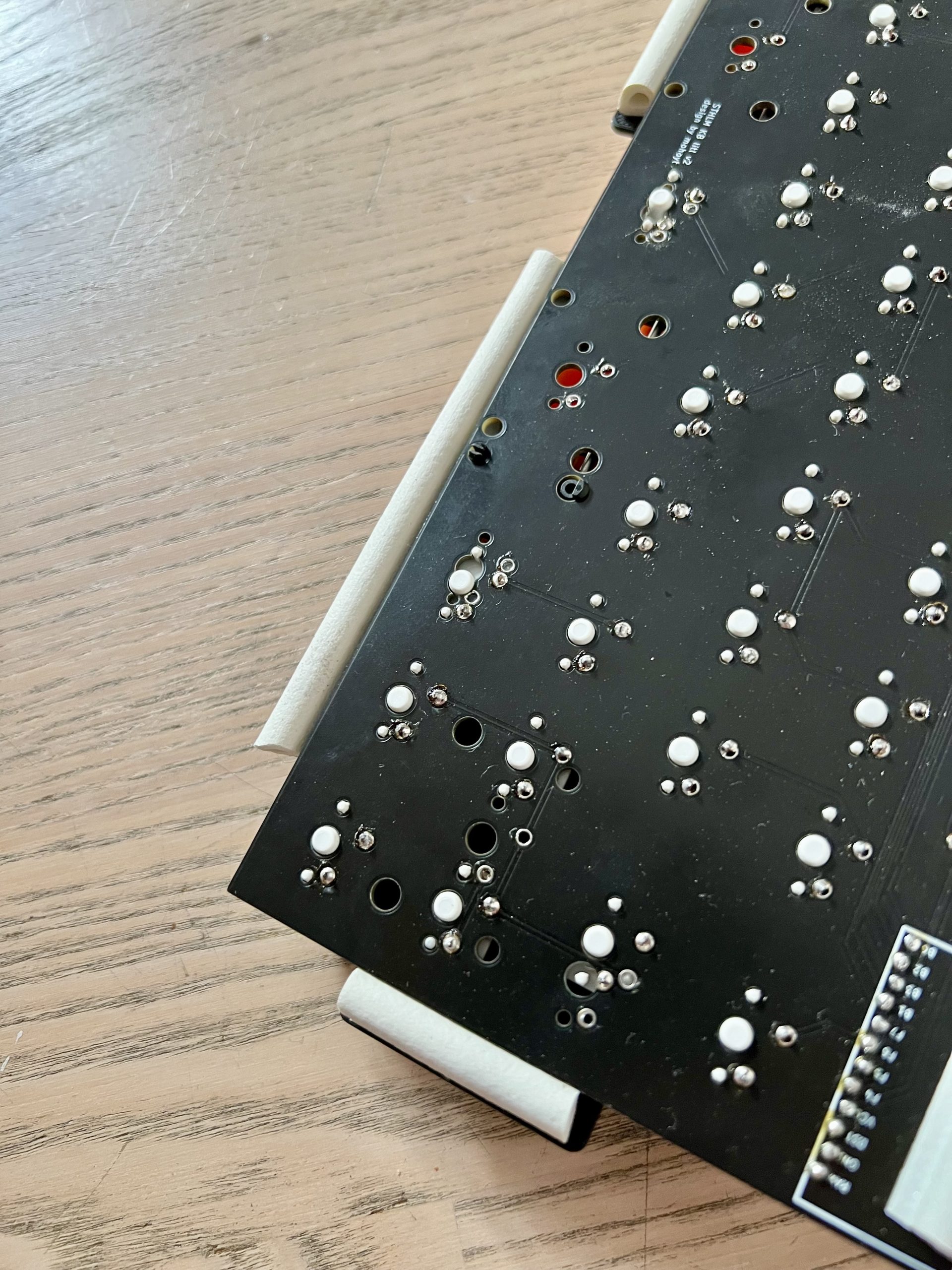
But first I needed something to make a case for. A while back I had some quality issues with some Litl boards that I had produced. I had hurriedly added a key switch option on top of the encoder mounting point at the top to give users more options for building, but had negated to adjust a trace that got in the way. This resulted in a net on the board that shorted to ground and caused super messy behaviour if you typed one of the keys in that column. Fortunately I spotted this fairly quickly before we had dispatched many of the boards and so we didn’t have to do too much disaster recovery. In the end affected users could opt to get a new board or make a small trace cut to limit the short.
But this meant that I had a fair few Litl PCBs with a correctable fault lying around collecting dust. A perfect test vehicle for some 3d printed cases. Normally the Litl keyboard comes with a base and a plate and forms a sandwich style mounted case. Because the trace short issue had only affected the PCBs, I had a surfeit of only them and no matching plates or cases. So any case that I designed and printed would have to include a plate (if I wanted to have a plate – and I did). This really didn’t add too much complexity at all, and if anything gave me some more options of how to mount the PCB and the typing surface.
In the event where I saw the neat printed and finished cases, I also heard about an interesting budget mounting technique using insulation sealing strips to sit between the plate and the case thereby pinching and suspending the board on a somewhat soft surface. This gave a more flexible and dampened feel than some other gasket mounts and much more dampening compared to the sandwich mount that I have been used to with the original Litl case. Coupled with a 3d printed plate which would be noticeably more flexible and bendy than a aluminium or FR4 plate, this was going to be a well dampened keyboard.
Version 1
I started the design process with the plate as I knew that was going to determine the ultimate size of the board, and it was also a part of the design that was fairly fixed – it was too late to make any changes to the PCB for example. I used the same plate generator that I used when making the Litl top plate for the traditional case and exported that to a DXF that I then loaded into Fusion 360. From here I gave it some margins to allow for keycaps not to hit the case edge then added tongues on 3 of the four sides to mount into the insulation sealed gaskets. Due to the size of the plate and the size of my printers print bed I had to make this part (and all the other main parts) in two pieces and then affix them together with joins and glue once they had been printed out.
With the plate shape mostly underway, this gave me a good idea for the sizes and tolerances of the main case that I could start to design around. I designed the case body as a solid piece that I then planned to cut and print in a top half and bottom half so as to sandwich the plate and gaskets in the gap. I started with a solid cuboid that I then started chamfering and filleting to get the shape that I wanted. The Litl board has exposed diodes and controllers along the top and I think that it made sense to expose them in a nice way so I made relevant cutouts for that with the later intention of inserting an acrylic window there too.
Once I had a shape that I was happy with, I then focussed on cutting it in half to make the sandwich style case. As part of this I wanted to ensure that it fit in a snug, but not too impossibly tight way. So any cutouts that I had on one side had to have cutouts matching on the other side too, but with just enough tolerance for them to fit nicely. I was happy with the work that I did here as it worked first time, required no sanding to make fit and didn’t wobble excessively. I later learned much nicer ways of doing this in Fusion so can probably accomplish the same thing with less work next time too.
Now that I had the case split on the Z plane I needed to figure out how it was going to be held together in its finished form. I had a bunch of M4 heat set inserts that I had used in a previous project around, so these seemed like the obvious choice. I created holes in the top inside of the case in Fusion with the screws being mounted from underneath. This hid them nicely once the case was built. I think the finished appearance of well set heat set inserts in a model looks really smart and professional.
The final thing that I had to do before I could start printing the first version was to split the model in the Y plane too so that it would fit on the print bed of my Prusa. I chose to split the top and the bottom parts of the case in slightly different places so that I didn’t have one weak line all the way through the model. Again, like the mount from the top to the bottom I made various dowel style features that enabled the parts to be joined and then glued in place correctly.
And with this, I was off to the races and was able to start printing the first version of the case. I started with the plate so that I could immediately start assembling my new case while the rest of it was printing (I’m not always one for patience). This didn’t take too long and soon I was seeing if my plate generated print file fit key switches correctly. To my slight surprise it did. It was a really bendy piece of material though (being only 1.6mm PLA) which I was a little concerned about, but after mounting switches and the PCB it seemed more rigid in a good way. I wonder how pure 3d hardwired boards cope with this? Perhaps there is some sort of bracing that they employ here to limit the bed a little if there is no PCB to help at all.
Next up I sent both pieces of the top to the printer (they fit on the same print bed in an interlocked sorta way) and finally the bottom parts both separately. These ones took a while, but I printed them overnight and when I woke up the next day they were there and looking great!
I did a test fit of the parts now that I had installed all the switches on the plate with the PCB under. The two halves of the case were a little loose at the joint as I didn’t make it thick enough (the edges of the case weren’t really thick enough to allow for a big dowel pin). But I was planning on gluing the halves together anyway so this wasn’t really a big deal. All was looking good so I went ahead with the gluing and had to wait a little longer till everything was dry enough to play with it more.
The next stage was adding the heat set inserts into the case. I used M4 ones for inside the case on the top half and then had screws attached from underneath holding both parts together. The insulation strips were attached to the bottom of the plate and then the plate was sandwiched in-between the two halves of the case. It was a little tight as I had only allowed just enough room for the 1.6mm plate thickness + the insulation thickness, but I was able to tighten it down easily enough with the screws.
I had some cheap black keycaps lying around from a purchase just waiting for a keyboard to go in, so these were the perfect ones to test this concept with. As they were cheap (and fairly nasty) caps they didn’t have all the sizes that I needed, so I had to have a right shift that was not only the wrong key, but also the wrong size. Not the end of the world, but some people like keycaps to be totally perfect before they start using a board. I’m not one of these people.
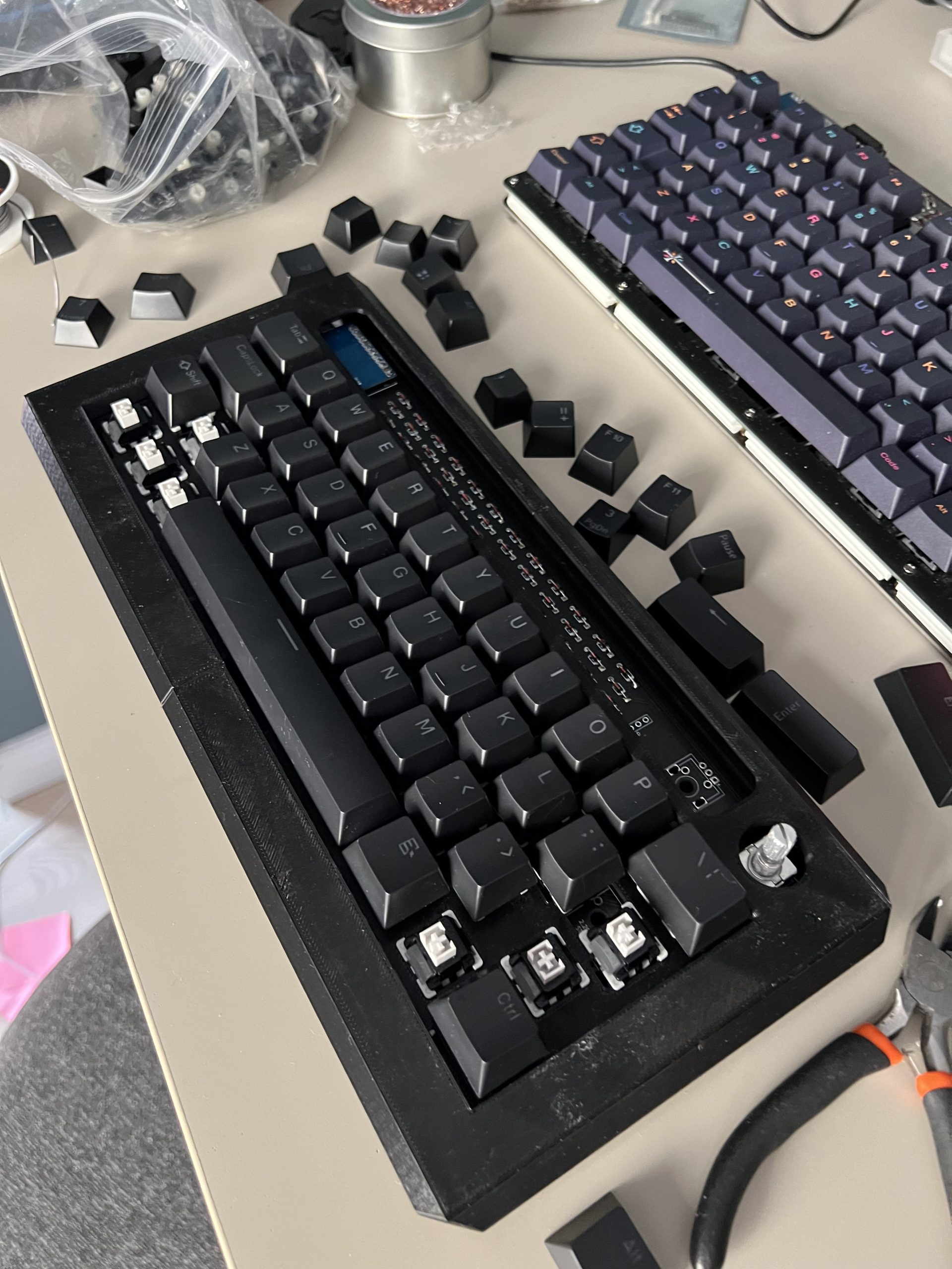
Then it was time for some testing! I basically just used the board as my daily driver for a couple of days to get the feel of it and see if it was something that I could get on board with (pun most intended). I wanted to see if there were any design choices that I would refine, or any serious issues that made it a pain to use.
There were a couple things that I came up with (nothing serious though):
- The corners were too angled and sharp. I really should have done the corners and chamfering in a different order, but this was something that I could easily fix in fusion ready for the next version
- There were no feet (and the whole bottom of the case was flat on the desk) so the typing angle wasn’t ideal. It’s a 40% board so this wasn’t that bad, but again something easily corrected in the next version when I could add M4 holes in the corners and enabled the use of the cone feet that I designed earlier
- The position of the plate was a little on the low side so the encoder collided with the hole that was cut for it. The cutouts in the main case for the plate to fit did not go up enough to enable the encoder to sit in the middle of the hole. I could change the encoder hole position slightly in the next revision and also enable the case cutouts to be larger. The screws and the insulation hold the plate tightly so it doesn’t matter if there’s additional wiggle room there.
- Some of the joins between the two halves weren’t amazing, especially at the lower end of the screen as this was very wobbly, so I needed to strengthen that in a future version.
But even with all of these flaws I was able to use the keyboard for a while and also measure out the perfect size acrylic window to fit in the gap at the top. I quite liked the super cheap grey wood v4 switches too. The whole board actually sounded really good too. Not bad for a budget linear.
Version 2
With knowledge of the failings and limitations of the first version I was able to jump straight in to making the second one. I quickly corrected the flaws in the bullet points above and pressed print.
All printed out well and I was ready to embark on the journey of sanding, priming and painting 3d models.
Step one was a rough sand to get the most of the layer lines off and smooth out edges that had stuck a little more than expected in the corners. This I did with 80 grit sandpaper. Possibly a little too on the coarse side, but it actually was one of the times that I didn’t hate sanding as it was so fast…
Next I had bought some spray filler that looked like it would work on plastic (though I think its original use for was car bodywork). I think this was pretty nasty stuff owing to the volume of safety labels on the container, so I made sure to spray this outside and as far away from anything as possible. I did a couple of coats in the end with a little bit of 120 grit sanding in-between and it did a really good job of filling up a lot of the remaining layer lines and making the overall finish smooth.
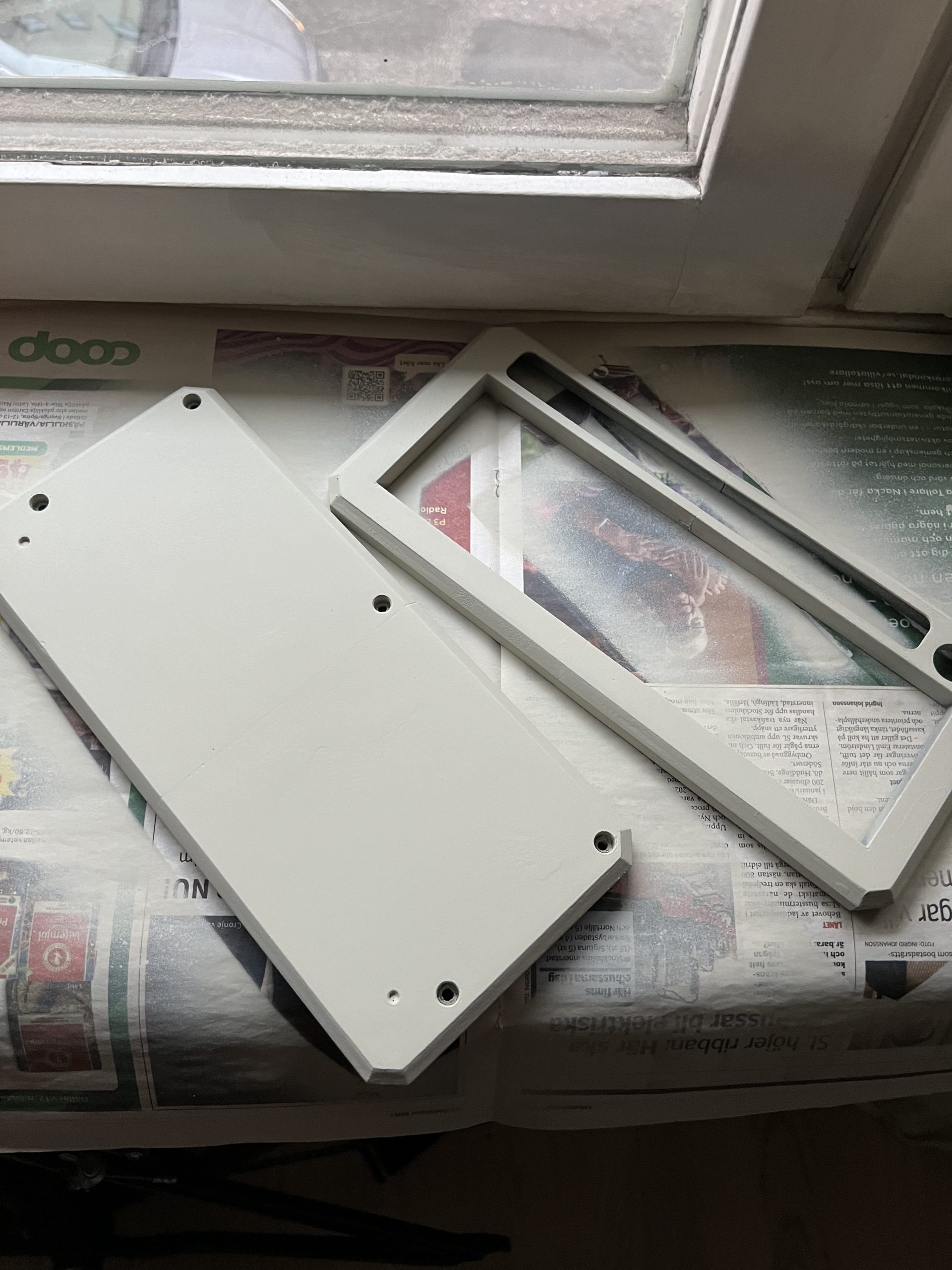
Next up was primer. I’m not sure if this was strictly necessary as the filler layer may have been a 2 in 1 filler and primer, but I figured that I had the can of it and an extra coat wouldn’t hurt. So primer it was. I think this made it go a little darker in the end to a light grey from the more white of the spray filler.
My original intention was to find a bright yellow paint and a clear coat varnish for the final finish so that I could do a lot of layers and get a great sheen and look to it. But while wondering around a home improvement store I found a great shade of yellow in a seemingly 2 in 1 paint and lacquer product.
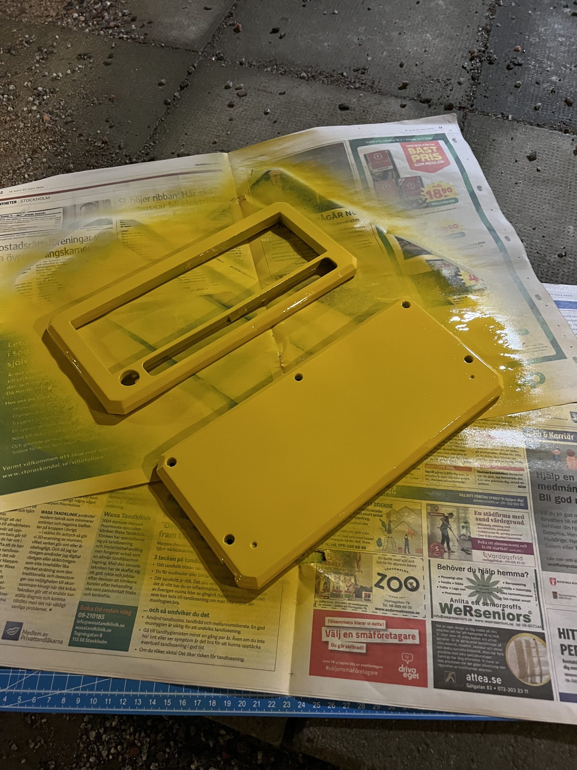
This went on really glossy, and it was fairly thick, so it also helped cover up a lot of the blemishes that had remained from before. I did a few coats of this before calling it quits as there didn’t seem to be any difference after 3 or so coats.
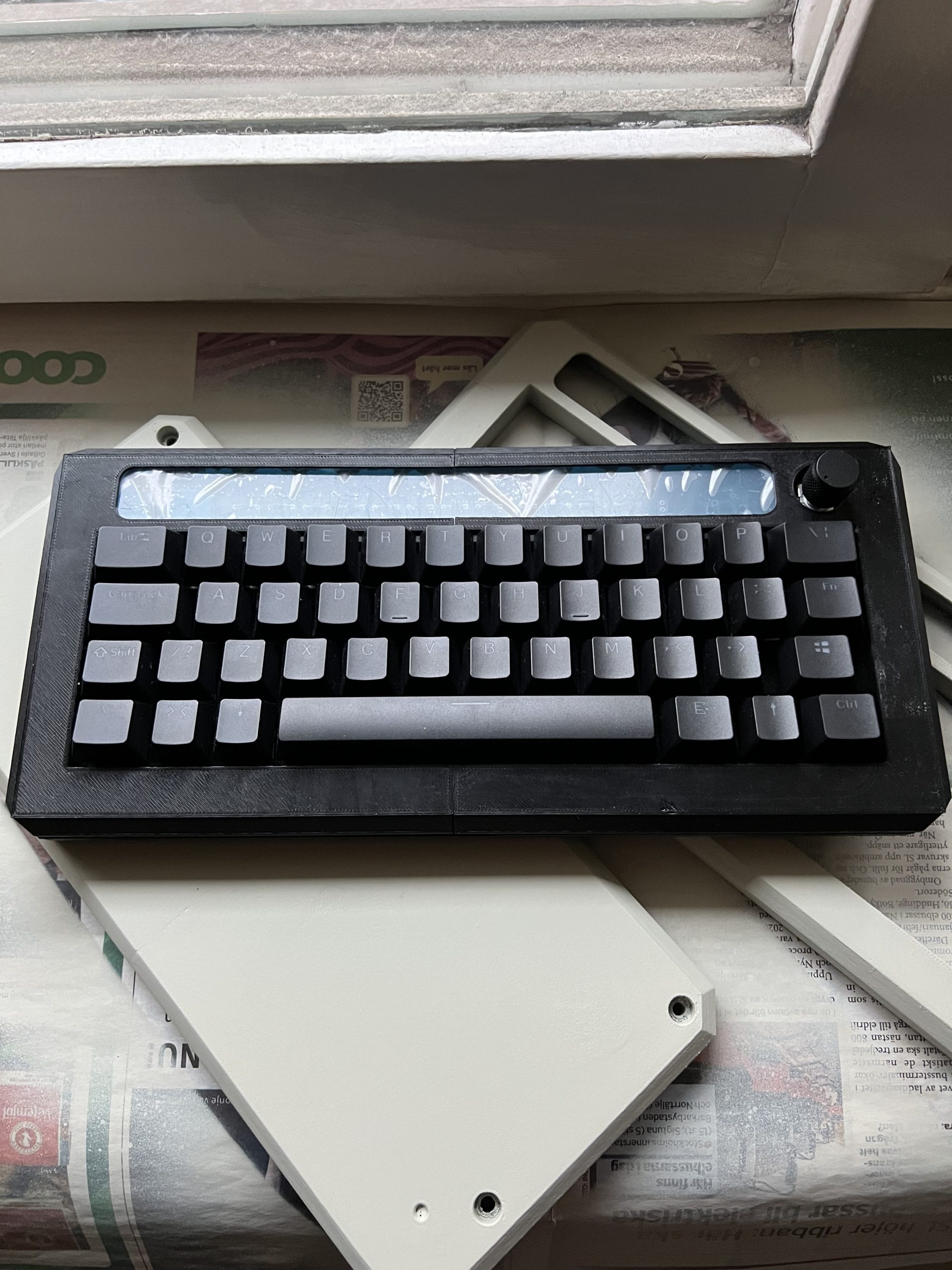
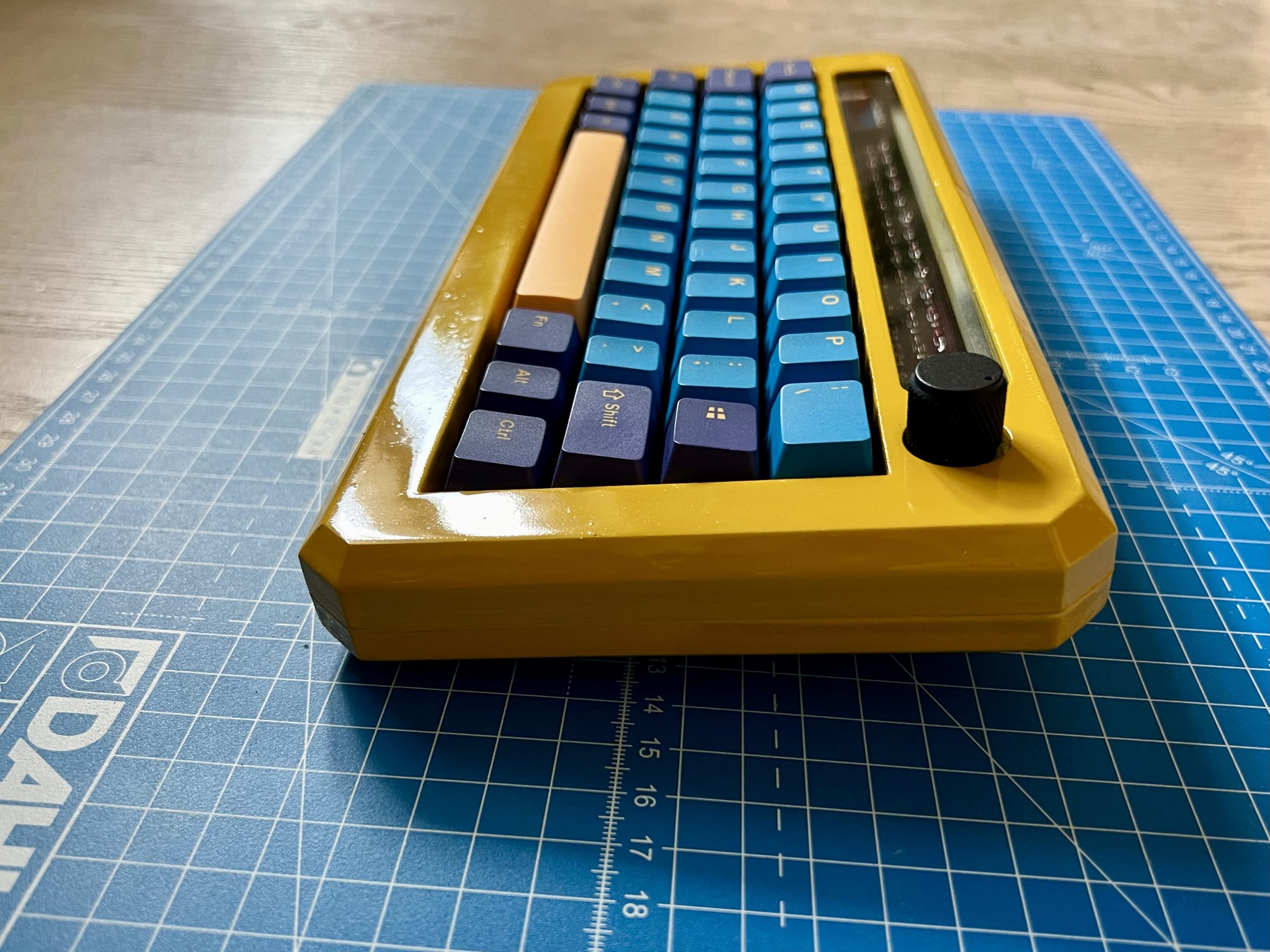
To match this wonderful shade of yellow I had some GMK Nautilus clones that I had bought a long time ago that would be perfect, or at least I thought so. So as soon as the case was dry I joined it together, installed the plate and then the keycaps. This is when I realised the shade of yellow wasn’t exactly the same as the space bar. Never mind, it still looked great.
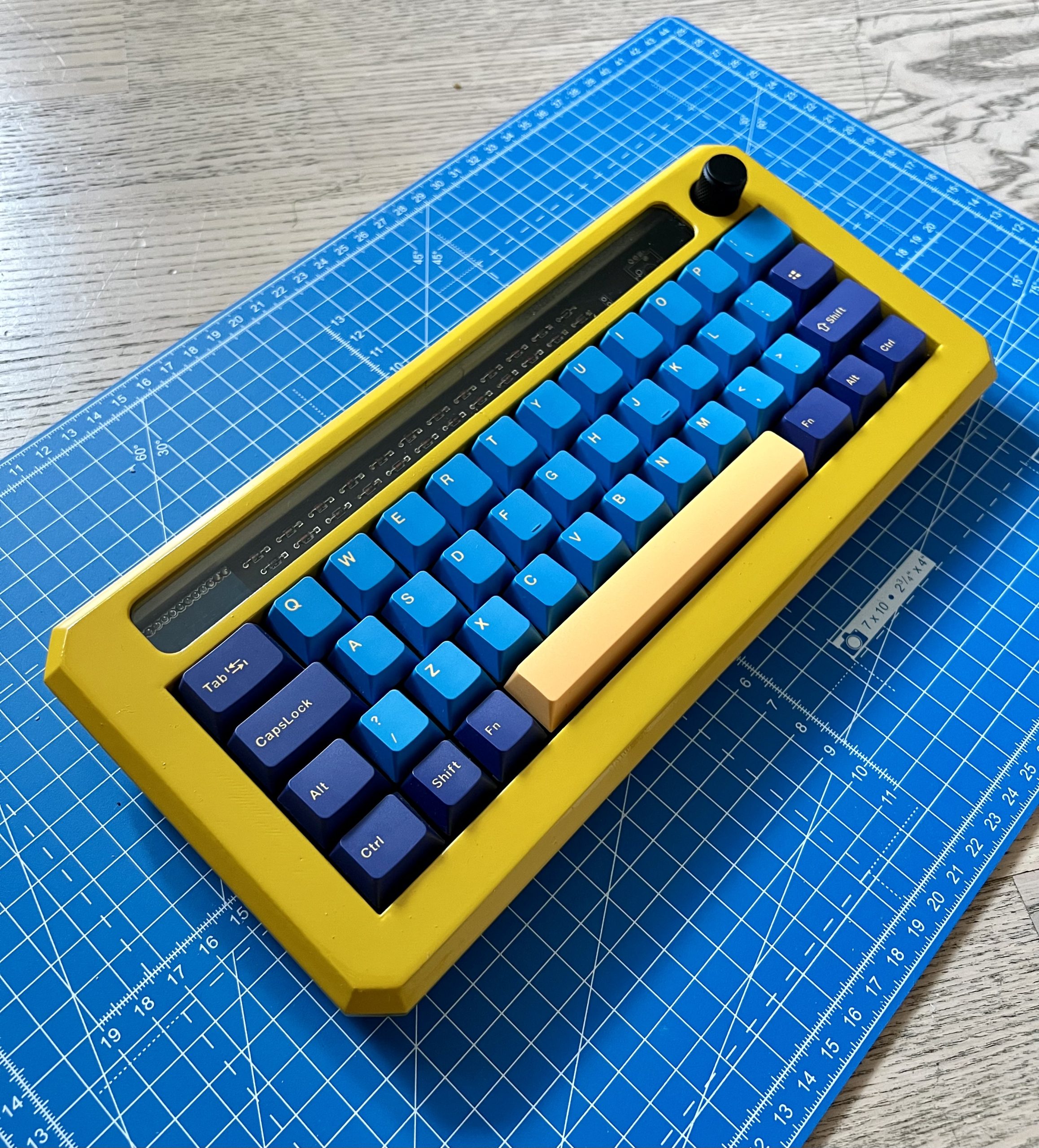
The window at the top worked out really well too, almost looking like it wasn’t there once I had removed the safety film. The new cone feet worked like a charm too and made the typing angle much better.
All in all, this worked out to be a great project. I found a home for the abandoned Litl board that I had, learned about 3dp finishing techniques and improved my Fusion 360 modelling skills. There’s still some things that I would improve more if I made a new version (and I’m sure I will in due course).
Improvements for next time
- Better ways of joining the two parts (I think the dowel pin method that I went for was a little on the loose side) – maybe sliding rails could work better and allow for a glue-less way of joining everything
- Try a different finishing paint. See if a separate paint and clear coat is better than a 2 in 1
- Use screws or something else to attach the acrylic screen. Glue was fine, but it was easy to push the screen and dislodge it, and excess super glue on the screen was a little visible in places
- Try putting an OLED in the window, or some RGB lights in there to show the status of the layer or shift in a relatively subtle way
- Build the angle into the keyboard instead of building a flat keyboard and relying on cone feet. I think this might increase the complexity of the design, but could give a more premium feel to the overall board.