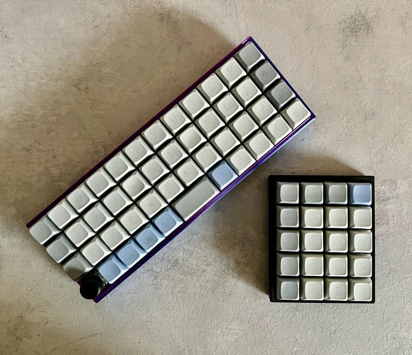
Choose Your Own Adventure (or CYOA) Ortho is a keyboard that I designed and released recently under a CERN Open Hardware license. It is a simple Pro Micro compatible ortho PCB that you can freely adjust to your preferences by snapping off rows or columns to make your perfect Ortho board.
The board is a 5 row x 12 column board to begin with but with the perforations on the board you can make it almost any size down to 3 x 3. So you can build ortho layouts like the Preonic (5×12), Planck (4×12), Gherkin (3×10) or even a macro or num pad.
To go along with the PCB I also released a set of 3D printable cases in all possible sizes for the board. So someone who wishes to print their own case for this keyboard is able to do so!
Background
The idea for making a board like this was born a little out of wanting to experiment with different PCB design styles (in particular with the perforations and snappable sections), but also to make it easier, more flexible and cheaper for people to try out different ortholinear layouts. Ortholinear layouts different from the traditional staggered layouts in that they have the keys arranged in a grid rather than with a horizontal offset, this can improve the typing speed and feel for some users (but as with a lot of things in the keyboard world, everyone has their own opinions).
When I was getting my first mechanical keyboard I did look into the somewhat budget and slightly out there options like the gherkin and planck boards as they looked really neat and had fewer keys (so less expense) but they seemed to also have a much steeper learning curve than most of the standard staggered 65 or 75% keyboards. A couple years and a few keyboards down the line I wanted to take another look at them. They’re not super complex design wise as they’re really all just grids, so entirely possible to make yourself or even hand wire yourself. But I couldn’t decide which one specifically I should try. Did I really need number keys? Do I really need a function row, or could I live with mod tap on lots of home row keys?
PCB
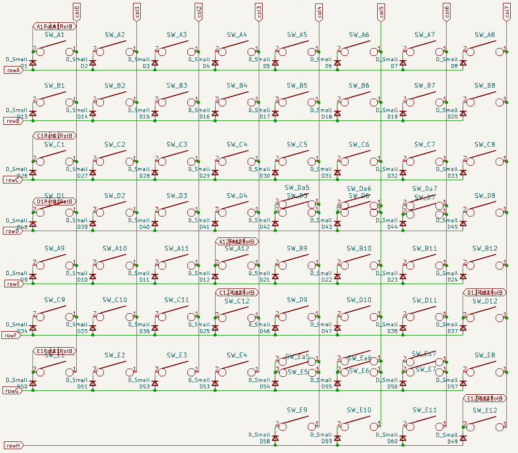
So I figured maybe it might be possible to have all of these in a single design. They’re all just grids of keys right? I had seen a couple boards in the past that had snap off sections – and I wanted to give this a go myself. The first step was figuring out how big I could go in the first place. As I’ve said before, the Pro Micro footprint has 18 usable pins. The biggest board that I wanted to go for was the preonic – essentially a 5 x 12 grid. This meant that I needed 17 keys if I went with a standard matrix shape. But that’s not always the most efficient way of laying it out. If you fold it a little then you can support 5 x 12 = 60 keys with a 8 x 8 matrix. And this would only use 16 pins on the Pro Micro instead of 17.
Another challenge that I had to contend with was ensuring that with the matrix design and the routing of the tracks I could still have it functioning when rows or columns were snapped off. As long as I stayed organised with the routing and was smart with the matrix design then this wasn’t going to be too hard, but it was an interesting challenge to design around. This is the matrix design that I ultimately went with.
Because I had two extra pins on the Pro Micro free I was able to add support for a single rotary encoder in a number of different positions too. I figured I needed to give as much flexibility as possible in this case so there are 8 possible places to put it: the 4 corners for the three different row height combinations of the board.
The other flexible section that I added was in the support for optional 2u keys (1 or 2) in the middle of the board for mini space bars for the 4 row and 5 row layouts. It didn’t really add that much complexity to the design either (just additional holes for stabilisers) so it was a good addition to make.
Take a look at the different layout options in keyboard layout editor.
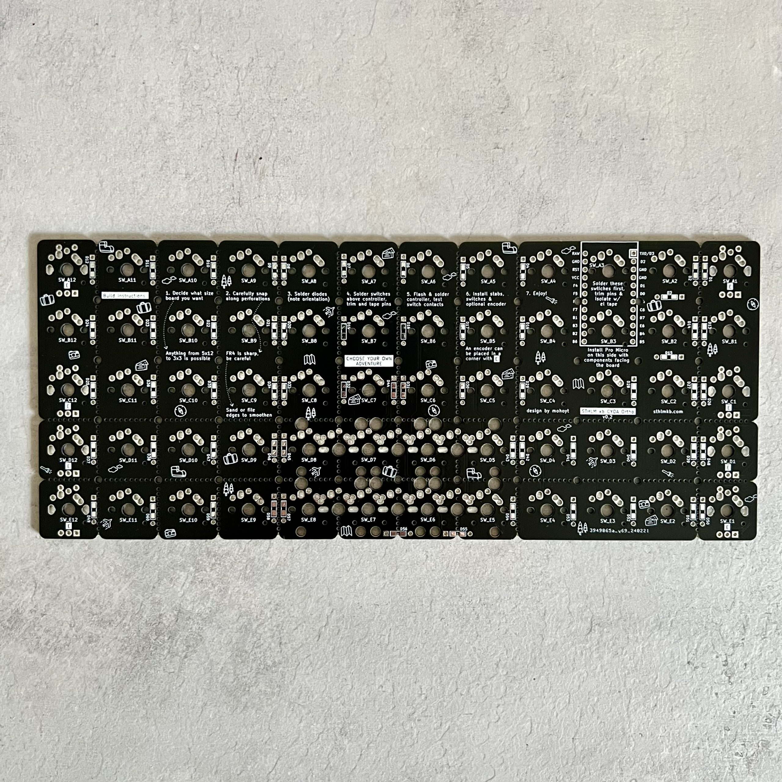
The PCB routing too a while due to the aforementioned perforations and finding elegant places to hide the diodes and the pro micro compatible controller itself. In the other keyboards that I have designed I placed the controller at the top so that it was always visible (it was part of the design aesthetic), but I wanted to hide it in this case to make the board as simple and as clean looking as possible. This meant hiding it under the board (unfortunately at the expense of thickness and soldering complexity).
Keeping with the adventure theme I wanted to echo that vibe on the actual board itself, so there are lots of mini adventure graphics (like palm trees, compasses, maps and suitcases) on the back of the board. As there there was still a lot of usable PCB real estate there, I went ahead and added simple assembly instructions on the back too. I had started doing this a little on Större as well in explaining what different components did and how to debug things, but I think I will do this on future boards as it adds yet another learning opportunity for the builders of the board.
So that was pretty much the board design done! After a bunch of pre-order checks (in which I actually missed some obvious issues like the incorrect pro micro footprint) I ordered 5 boards to see how they actually looked and performed for real.
Case
This meant that I could then start diverting my attention to the case. As there were a lot of different combinations of board sizes I wanted to take this into account in the CAD design of this by parameterising as much as possible. So then the process of changing from a 3 x 3 case to a 5 x 10 case would not be overly complex. This was a great learning experience in Fusion360 and wasn’t too tricky after all. I think the most complex bit was in writing conditional statements for the standoff placements for the different case sizes. The holes in the standoffs ended up colliding in many cases which was not ideal, but ultimately I figured out ways around it.
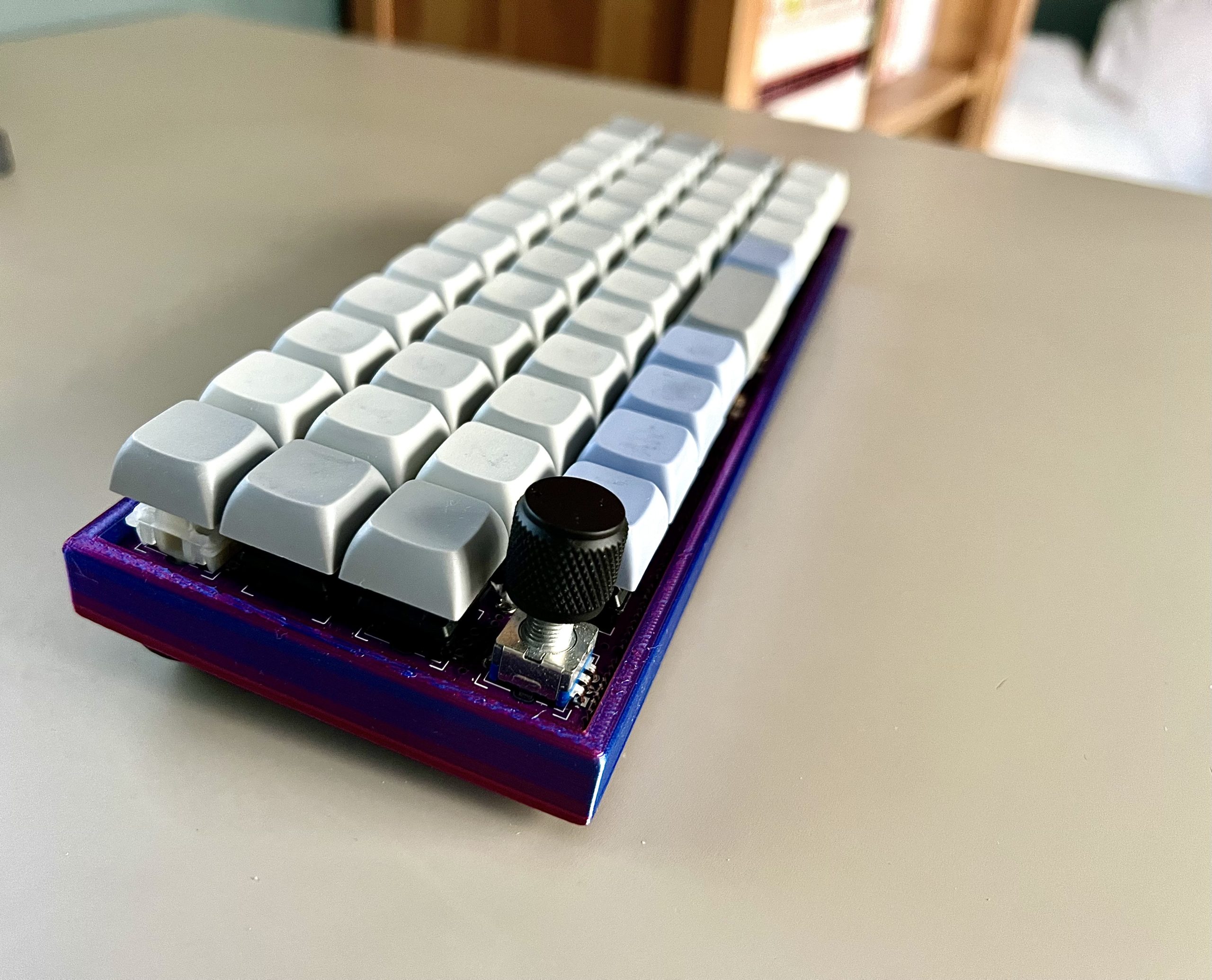
The case design that I ultimately ended up with was pretty simple though, it’s a tray with edges and a hole for a USB port for the controller. It has plastic standoffs with space for a heat set insert (which I think work really great) and additional holes on the base for cone style feet. It could be made a lot better, but it’s a start and shows what’s possible with this keyboard. The PCB itself has M2 holes in pretty much every possible place so there are many mounting options for people who wish to try things. A plate could also work nicely, and could be machined, laser cut or 3d printed, but again, this up to the end builder of the board for how they want to customise their setup!
Firmware
The final part of the equation was the firmware for the board. With so many different layouts and sizes of the board this was a little more complex than usual and meant that I had to have a whopping great 1000+ line info.json file with all possible configurations. But this was fairly programmatic and not bothersome to create and ultimately meant that end users would have a more straightforward setup experience.
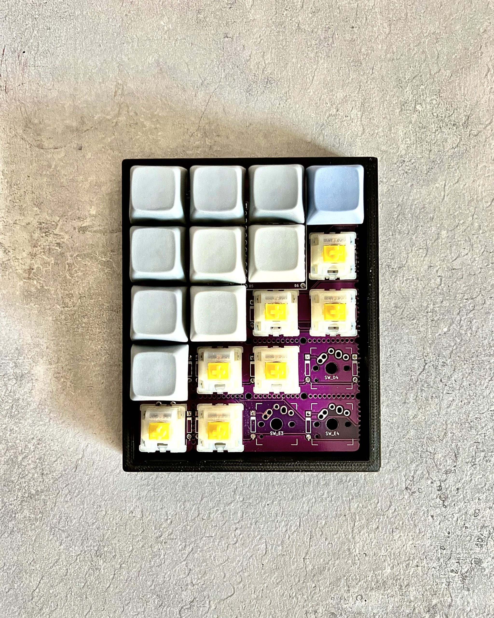
The test boards that I built for this keyboard were a 4×12 Planck in a red/blue silk PLA case powered but a regular pro micro and a 5×4 macro pad sorta thing in a black PLA case powered by a RP2040 Pro micro that I had bought a few of recently. They both worked as expected (thankfully) and I added these to the set of precompiled firmware should anyone end up building a board of the same size.
As with my other boards I also added Vial support as I think that’s a great and easy way to switch between and tweak the layouts that you have. This is more important than ever on a small board with a non standard layout. I would imagine that most users of this board would be somewhat familiar with QMK and be able to wrangle their own keymap together as part of this build.
Closing thoughts
This was a lot of fun to come up with and ultimately release out into the world. There were a lot of moving parts and dependencies, from the electronic design to the mechanical hardware to the firmware that powers it all and it was fun to sit at the intersection. Maybe I spent a little too long making sure that it was complete and perfect before releasing it, but I want to make sure that anyone building one for themselves has the best experience possible.
As I touched on earlier I made a couple errors with the PCB footprint sizing which meant that my prototype boards were pretty hard to use with standard pro micros (but I managed!). I’ve added more things to my preflight PCB checklist so that I can at least have half a chance of catching these things in the future.
Now I just need to come up with something else exciting and keyboard related… watch this space.