It’s about time for a new electronic and music themed project right?
This time I wanted to tackle the Minichord. It’s a wonderful little instrument based on the Suzuki Omnichord, but, as the name implies, is much smaller and not quite as full featured. It’s open source (I love open source hardware!), is designed by a smart chap called Benjamin and you can find out more about it here: minichord.com
I think I originally came across it from YouTube, and seeing some neat YouTube short of someone playing it. It reminded me a little of the other chord based composition instruments out there (like the Orchid, and I think there’s another one with a joystick too). But this was a little less polished (in a good way), more diy, and happened to be open source.
You can of course buy kits or the finished version from the maker on their site (I think that they do their distribution via Seeed Studio), but when I looked there was a crazy long wait time and it wasn’t mega cheap either.
So, as with many other projects, I decided to go ahead and see what it would take to make one myself!
Planning the build
My process with planning these sorts or builds is pretty simple:
- Find the schematic, kicad files or gerbers.
These are the production hardware files, or enable the production hardware files to be made or generated. Gerbers are best (as that’s what I’d typically send to the fab) but it’s also nice to have a kicad file too as then you can dig into the design a little more, learn how and why it works and also troubleshoot it if there are problems. You can also generate BOM and CPL files much more easily from Kicad, and choose and organise the PCBA components that you’ll place from JLC with a wonderful plugin. Occasionally there are some designs in other formats (e.g. Eagle that can be opened in Fusion) and they seem to be pretty good too, but I’m much more used to Kicad these days).
In some cases, and ideally in only really simple circuits, there is only the schematic and you have to recreate it in Kicad and design the layout yourself. This takes much longer, but it was how I got lots of practice in Kicad building (and figured out how to not make many mistakes in the process).
For some Eurorack modules the main PCB is shared and available but the panel is often not. This means that I’ll have to whip up a panel design in Kicad (or some other software) if I go down this route.
If you can’t do any of these things, then you’re basically stuck and it’s not worth pursuing the project any further unless you plan on doing a lot of reverse engineering. - Get the BOM and figure out rough costing.
This kinda gives me a ballpark idea of whether the project is worth pursuing further. If there are 1000s of components that I will have to place manually, or there are some components that have impossibly long lead times then this often kills the project here.
But when there are issues at this stage, there are normally some creative ways to work around them. Solutions to these issues could be things like:
- Waiting until the parts come in (however this could be a while, the chip shortage days are still fresh in mind)
- Reordering specific parts to JLC (either from their supplier or another company on JLC with surplus – this is what I did with a component on Plinky)
- Accepting that you can’t get the component done with PCBA and ordering it from Mouser or another source and then soldering it by hand (but this is best done with actually hand solderable components (so not QFN packages or 0402 size things, I’ve done this with some electrolytic SMD caps recently))
- Changing the component or the footprint (or both) on the board to something that you can source or hand solder. Occasionally there are some hard to find ICs that have been phased out, so you have to get creative with a different package or a different chip entirely. I’ll tackle this problem soon with V2164 VCA ICs that I will attempt to replace with SSI2164 ICs on a Mutable Instruments Veils clone.
I try and build up a relatively standard format Google sheet at this stage to track all the parts and pieces that I’ve ordered or need to order so that I can get a handle on cost. With this method, I can relatively easily estimate how much I need to sell the spare PCBs for in order to finance the whole project so that I break even.
- Take a deep breath and… order it!
But not without checking again and again for any issues in the gerbers, any issues in the placements and anywhere else that I might have screwed up. I have a checklist that I specifically use for ordering PCBs where I force myself to go through everything (heavily inspired by the Checklist Manifesto). - Wait for it to arrive, and order all the other parts that you’ll need so that everything arrives at the same time.
While manufacturing these days is pretty incredibly fast, it still takes a finite amount of time, and sometimes I don’t like to wait that long. So in the meantime I use that great Google Sheet that I created to figure out what other parts to order ahead of time and get all the supplier shipping timings correct!
So going by that great process planning list that I outlined above – I ordered some minichord PCBs. The main bump in the road was a lack of CPL file, so I had to figure out the placement for all the parts myself. This would have been a perfect use of the gerber-cpl tool that I built, but I hadn’t quite built it yet (this project was one of the reasons why I did!).
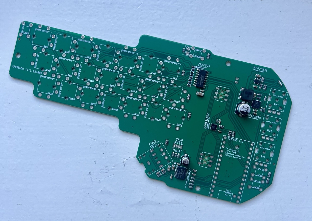
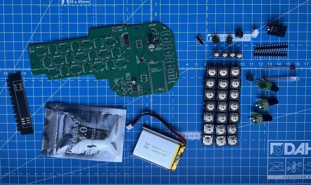
So after much manual measuring later, and also getting the origin for reference wrong and having to almost replace everything within the JLC PCBA tool, I was ready to order. Thankfully most other things that I needed for this project were easily obtainable on Mouser with the exception of the tricolour LED, the battery and the Teensy 4.0 (apparently this is some sort of controlled item at Mouser, but not at Digikey). Electrokit.com came to the rescue here!
This was my first project working with a battery – I’d kinda avoided them up until this point as there’s always a little more hardware and components required. But there was no way getting around it here. To be honest, there’s nothing really to be scared of, you just have to be mindful of polarity. The battery that I got had the JST connector reversed so I had to mount the socket the opposite way around. No biggie, and it worked fine.
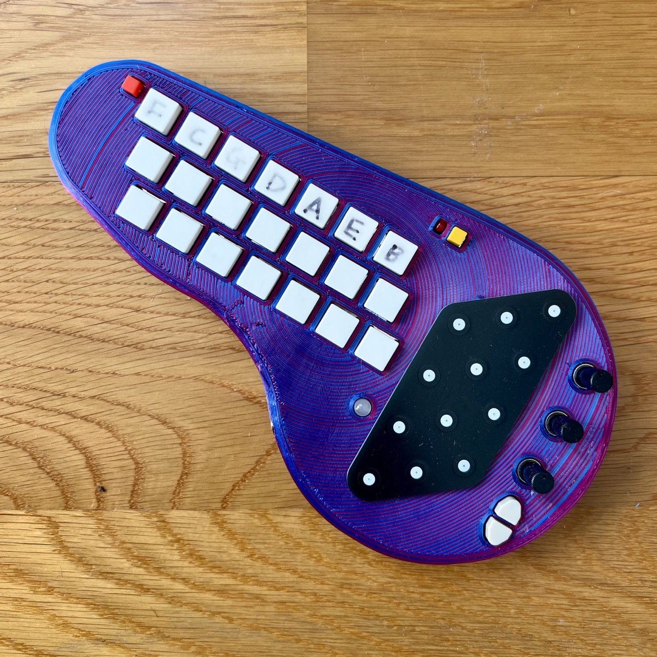
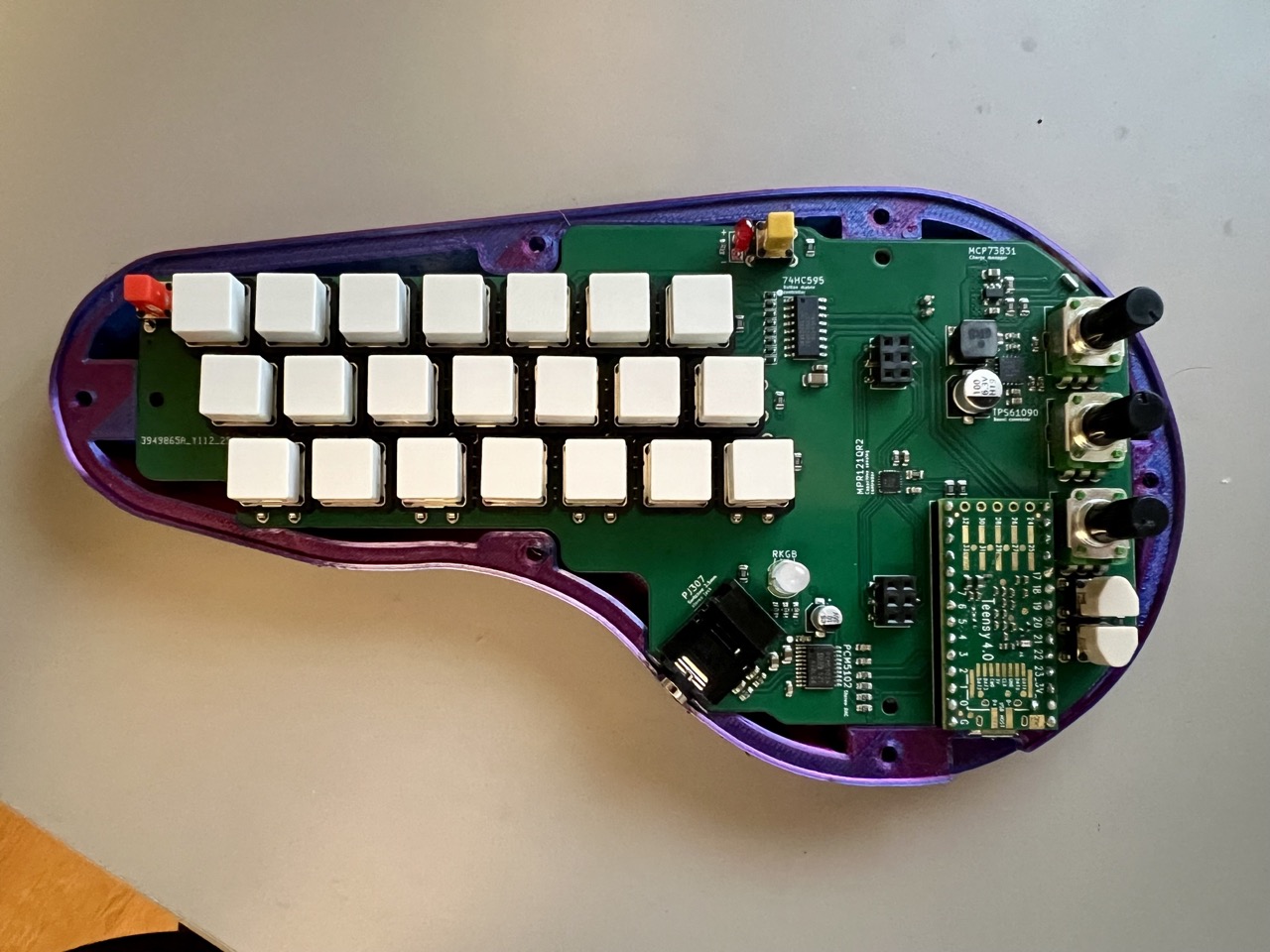
I made a couple small modifications to the case to fit a slightly larger battery, but otherwise what I printed was essentially the stock case design, in red-blue ‘3D’ PLA of course. It’s a tight fit, especially with the edges of the Teensy (which is mounted pretty close to the edge of the device so that the USB port is accessible for charging and midi. In a later version that I printed I also added heat set inserts for the case screws so that the plastic doesn’t get too chewed up after a couple attempts of opening and closing the case.
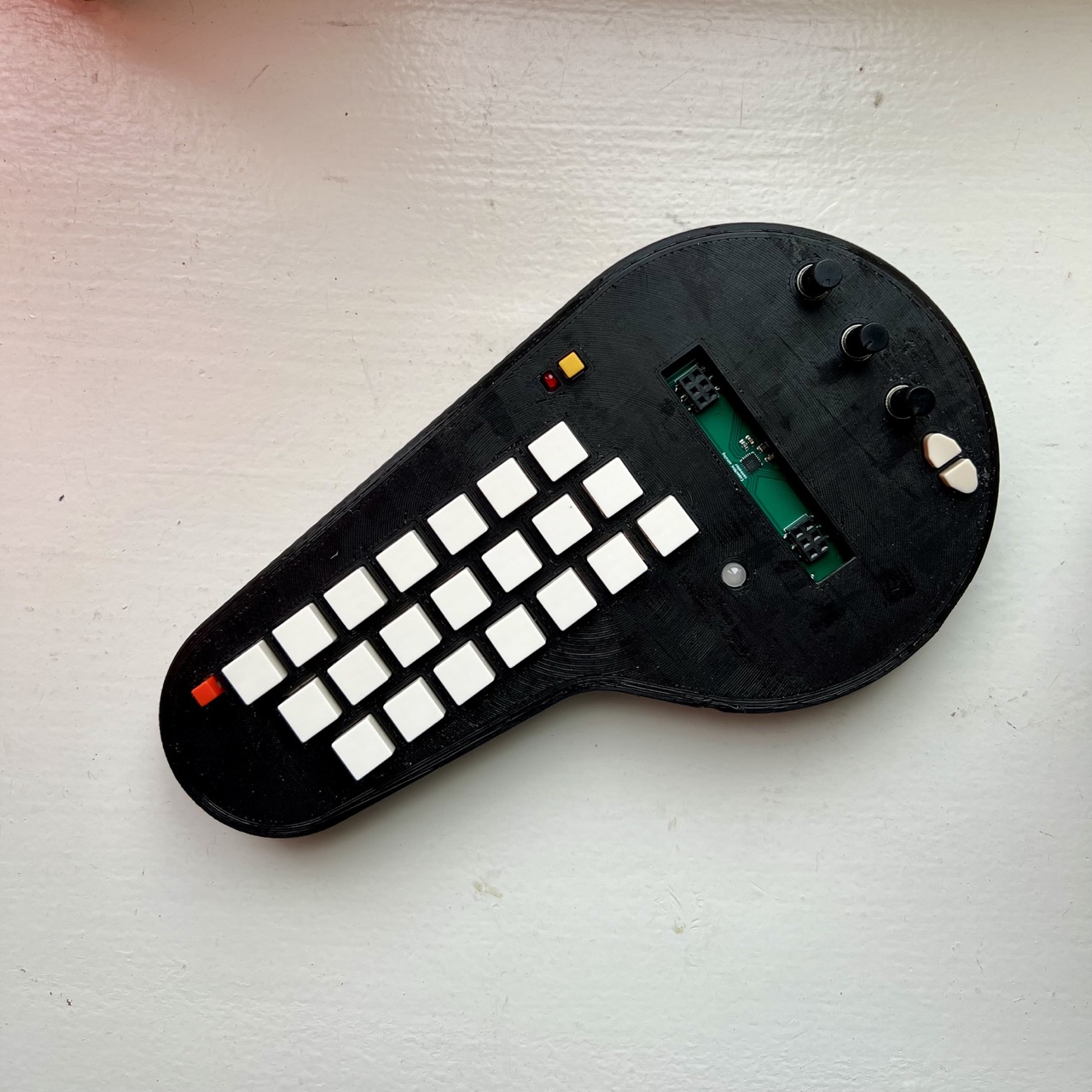
All in all the construction of the minichord was super pleasant. The instructions are great – the soldering was smooth – my only gripe was that the tricolour LED legs were really (perhaps unnecessarily) close together, so a little flux was needed and this increased the difficulty of the soldering somewhat.
Otherwise, everything went as planned, got everything connected up and stuck in a headphone cable to see if it worked. It did! The LED lit up real bright and I could see what mode I was in. I connected it via USB to finish the charging and then use as a midi controller for things. There’s a lot of potential and a lot to explore here!
A couple of rough ideas for improvement or tweaks:
The power switch headphone jack combo. It’s cool that it only turns on when there is a headphone inserted, and this saves on a power switch somewhere on the unit, but is this really needed? It adds a little to part complexity (instead of a regular stereo 3.5mm jack you have to find a switched one) and it’s not always obvious to end users.
A speaker perhaps? The combo of a battery and a headphone jack means that you always need wires, so there’s not a really clean way of playing the Minichord with no wires. A small speaker could be a neat option to enable this, but it adds much more hardware and battery drain so I see why it was omitted!
Final Thoughts
Another project in the books. It was fun. I learned a bunch. I have a cool instrument out of it. And I made a couple of gifts for family members.What’s not to like?
I have a couple extra PCBs for sale on Tindie still if you’re interested…