
After the fun of building a Plinky I wanted another project with a microcontroller, and potentially one a little bit harder to flash and configure. I’d seen some great demos and YouTube videos of Plaits by Mutable Instruments and knew of its almost legendary Eurorack status. I also have an Arturia Microfreak so I have some experience of the different voices that it can offer (albeit in a semi modular state).
Sourcing and manufacturing
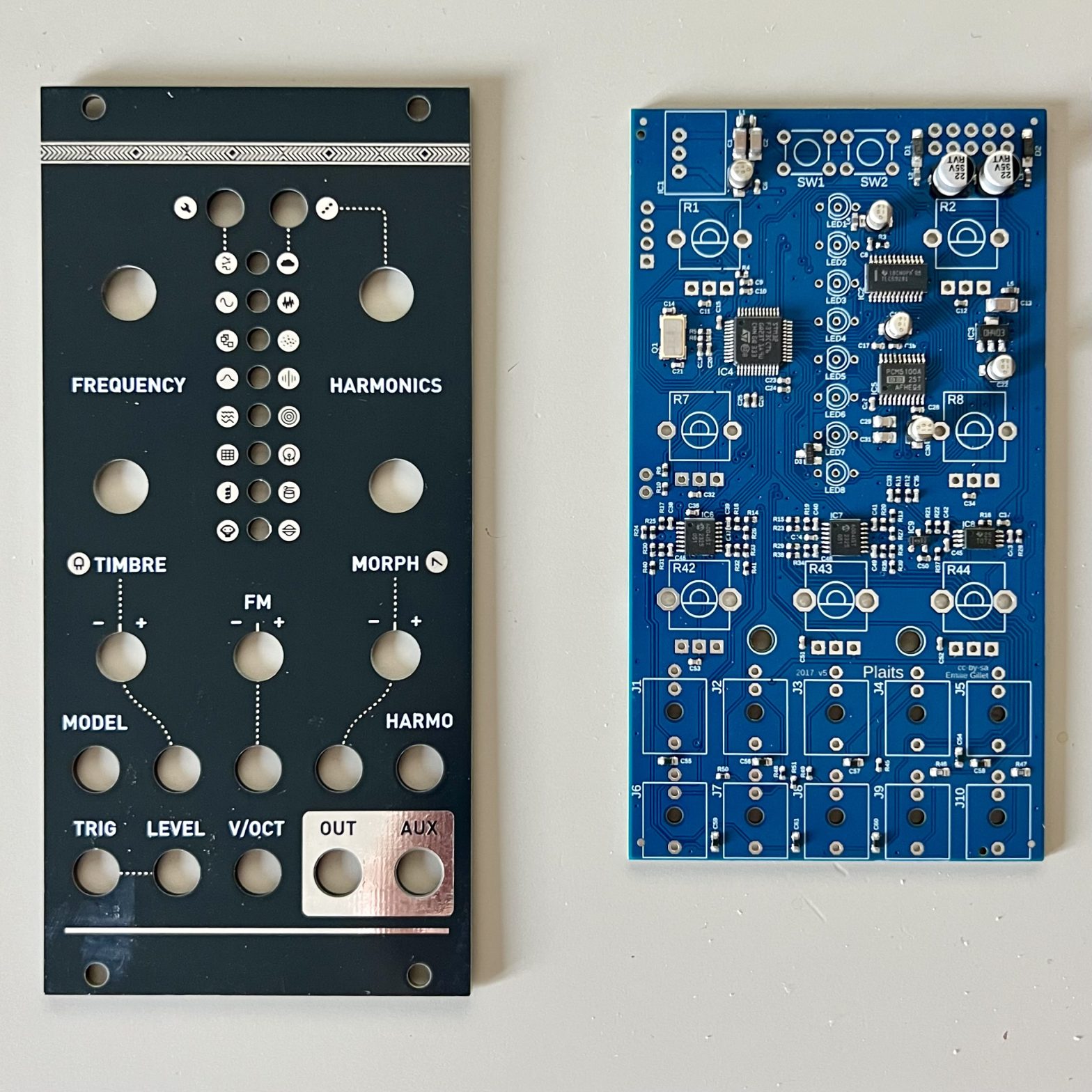
Almost all the Mutable Instruments modules (save for Beads) are available open sourced now so it’s absolutely possible to manufacture and build the modules yourself, or use the original schematic and design a smaller sized clone (as many people have done). While there are clones of Plaits out there in a smaller footprint (there is one called Beehive for example), I think that the original size is not too wide and the quality that went into the original design and placement of hardware elements is likely better than many of the clones out there. So I wanted to go with the original form factor. I started taking a look at the files in the Mutable Plaits repo. There’s a schematic and a PCB, both in the Eagle format which was simple enough to open up with Fusion 360. I’m not as comfortable there as with Kicad, but I managed to figure out what I needed!
All I really wanted to do was to generate gerber files for making the board and then also generate a BOM and CPL that I could use to place the components with a PCBA service. This was pretty straightforward with exporting production files from Fusion and this gave me Gerbers, a BOM, and a CPL. There were (completely unsurprisingly) no LCSC part numbers on any of the components so there was also a little work needed in enriching the CSV BOM by connecting the suggested Mouser components in the Excel BOM to comparable ones that I could source at LCSC and JLC.
This took a bit of time, but I think now that I’ve done this for a couple Mutable builds, I have a pretty good idea of the components that they use, so hopefully doing it next time will be even faster! I was then able to order the board at my go to place: JLC.
I also wanted a panel to go with this PCB to make it look as professional as possible (I was, after all, planning on selling the extra boards that I had produced), but I didn’t want to violate any of the terms set out in the Mutable Repo, so I made it look different than the original Plaits front panel (I went for a black theme) and made sure not to mention the word Plaits on it. To do this I refined the Illustrator file in the repo with Affinity Designer to set up the layers correctly and then used the excellent Gingerbread tool by Winterbloom to convert it into the layers needed for Kicad. I was, after all, going to get it made out of FR4 (PCB material) and wanted it arrive at roughly the same time as the main boards. I chose to go for Lead free HASL coating as I always tend to on boards, but I think maybe I should have splurged for ENIG as the gold would have looked much better than the silver, especially around the output jacks.
Flashing Plaits

Once the boards and my Mouser order with some additional parts had arrived I was ready to start assembling part of the module so that I could begin to flash them! Practically this meant that I had to solder on the Eurorack header cable, a 4×1 header for flashing and a 3.3v regulator that I bought separately from Mouser. The regulator was a little thick to go on the front board as suggested (it would have meant that the panel did not mount parallel to the PCB) so I opted to place it on the back, and had to reverse its orientation to make sure that it was connected correctly.
The 4 x 1 pin header had the pins (from top to bottom) RST, SWCLK, SWDIO, GND. For flashing these had to be connected to the equivalent pins on my STM32F0 discovery board.
The STM32F0 discovery board has 2 controllers on it. One for flashing and one for testing. If both jumpers are in place then it’s set up to flash the on board controller, if the jumpers are removed then it’s setup to flash an external one through the SWD pins.
This means that you can verify that your software setup is correct before connecting to the controller on the Eurorack module by trying to connect to the onboard controller first. To do this I made sure the jumper was in place and then I opened up the STM32CubeProgrammer flashing software and chose the correct device on the right hand side and then pressed connect. Thankfully, this all worked and I could see the current code of the on board controller on screen. I could then disconnect from the on board controller, unplug the STM32 discovery board and remove the jumper.
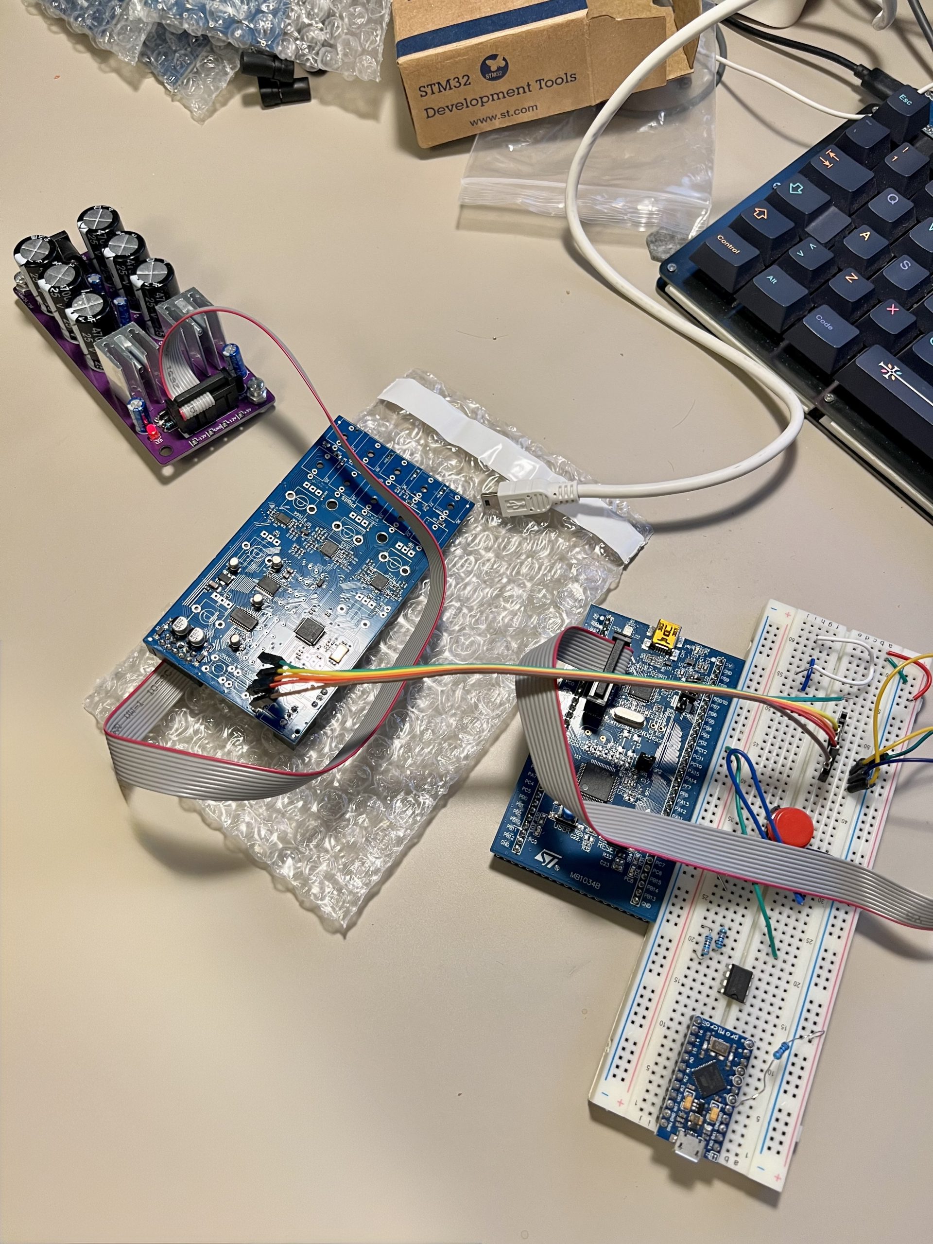
Then I wired up the 4 pin header on the Plaits module to the pin header on the discovery board and double checked that I had each pin connected in the right place. Then I powered up the module, powered up the discovery board and attempted to connect to the board within the STM programming software. I found this guide and this site pretty helpful with some of the connection setup.
This didn’t work the first time because I had accidentally swapped the two data pins. But once I realised this and fixed it I could then connect successfully to the board in the programming software. Then within STM32CubeProgrammer I could open the Plaits bootloader file and download that to the MCU and then I could open up the main file and download that to the MCU too. I then disconnected from the controller and unplugged everything. In theory, now it was all flashed and good to go.
Doing the flashing this way meant that I had to have a bootlaoder and a firmware file ready to go. And indeed they are possible to get, but I couldn’t easily find one for the newest v1.2 firmware file. You could obviously get around this by installing v1.1 then updating to v1.2 via the .wav file method, but I found these great instructions on an issue in the MI github repo to build the newest firmware and bootloader from the repo and then flash them to the device all through the terminal. Replicated below to help me remember for next time:
## SETUP (only required the first time)

# add PX4 formulae to homebrew
brew tap PX4/homebrew-px4

# install STM32 & ARM toolchain
brew install stlink open-ocd px4/px4/gcc-arm-none-eabi-48

# create projects directory if you don't have one and switch to that directory
mkdir ~/projects
cd ~/projects

# clone the mutable eurorack repository
git clone https://github.com/pichenettes/eurorack.git

# switch to the repository
cd eurorack

# clone submodules
git submodule update --init --recursive

## FLASHING THE MODULE

# switch to your checkout of the mutable eurorack repository

# note: change the path if you cloned it to another location
cd ~/projects/eurorack

# configure make scripts to point to the correct ARM toolchain

# note: you will need to repeat this step in the future if you are flashing modules
export TOOLCHAIN_PATH="$(brew --prefix px4/px4/gcc-arm-none-eabi-48)/"

# compile bootloader

# note: this is for peaks, but the steps are the same for most other modules, just change the path to the correct makefiles
make -f peaks/bootloader/makefile hex

# upload to device
make -f peaks/makefile upload_combo_jtag
Obviously you need to have the module powered and connected to the programming controller correctly in order for this all to work. But it did and it was surprisingly super easy in the end. Now I had flashed the module successfully twice so I think it was about time to move on to the next step.
Building the rest
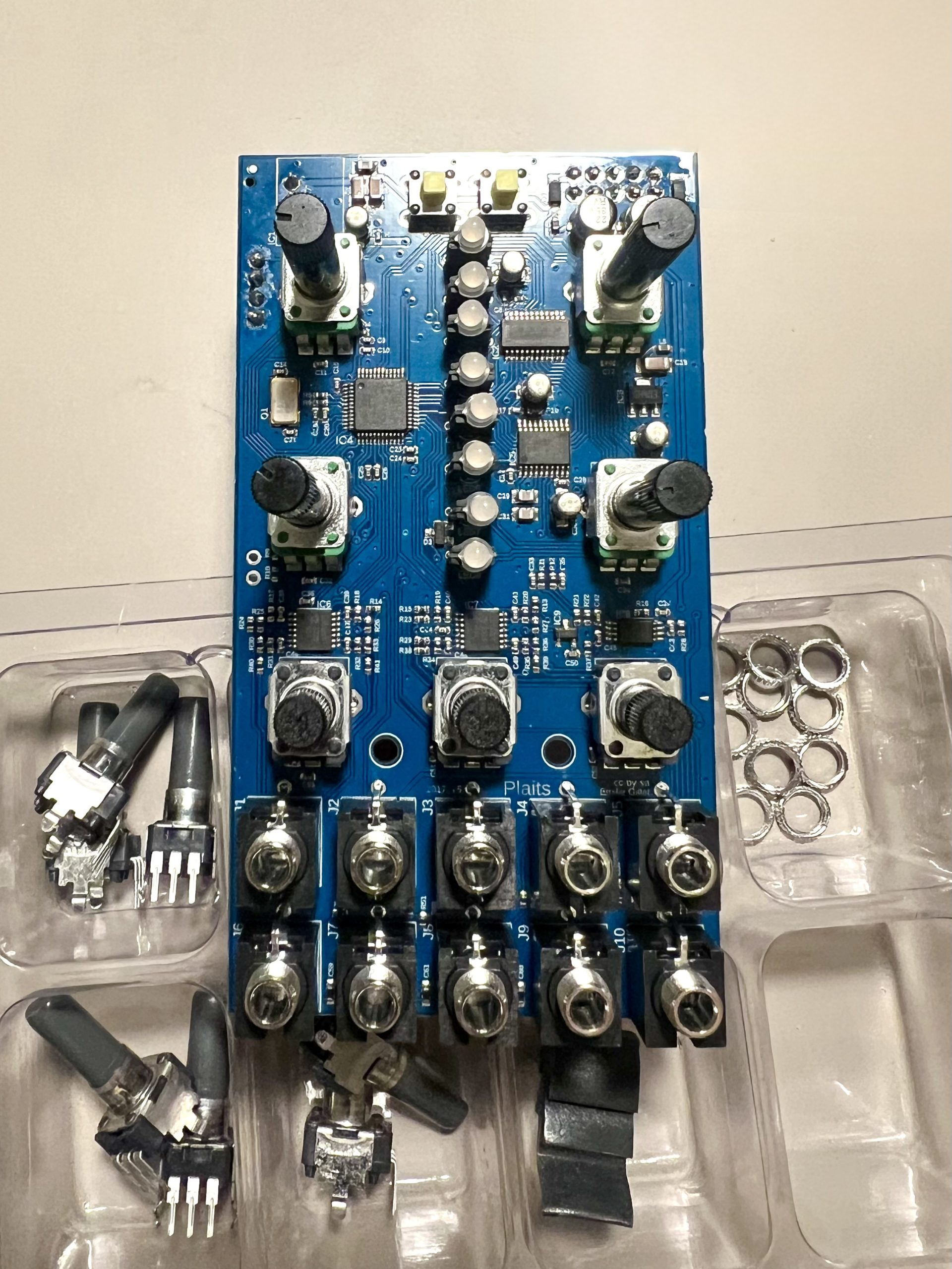
The next part of the build will be familiar to anyone who has bought module kits before where the SMD is pre soldered and all you have to do is connect the front hardware and panel. In this case it involved LEDs, 8 pots, a couple buttons and a fair few jacks. Not super hard to solder, but it’s always good to be cautious when soldering in the proximity of delicately mounted SMD parts.
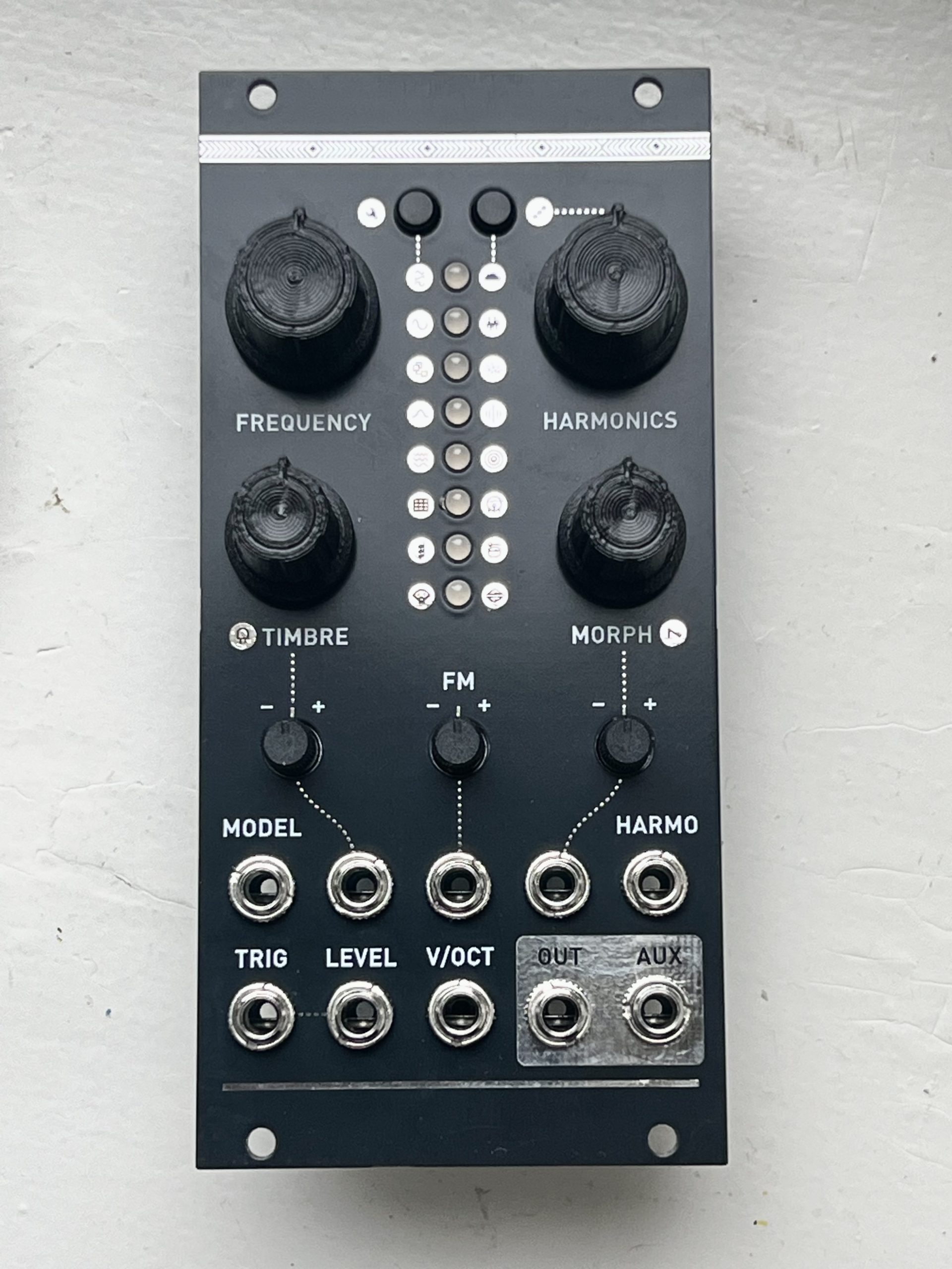
Once I had soldered the rest and attached the front panel it was time for the moment of truth. Would it work as expected? I plugged it in, not knowing if the firmware installation had indeed all gone to plan.
Lo and behold a little green light turned on at the top, indicating that it was in the first harmonic mode. I could then press the left button to cycle through the different green modes and the right button to switch into the percussive modes. To access the new firmware modes I had to press both buttons together, and then the function of the buttons would change so that they went up and down through all the modes, including the new orange modes (which include some really nifty and user customisable DX7 presets!).
There are a couple other functions that you can do with the buttons like setting the behaviour of the low pass gate and calibration. But once I had tweaked both of these I was ready to start playing around!
Once I had verified that all was working I took a break and some time to play around with the module itself. It packs a great range of sound into a fairly small and accessible package.
Then it was time to assemble a couple parts on the other boards and flash those too. Having done it once it was pretty easy to replicate another 4 times, and before long I had 4 successfully flashed boards.
Conclusion
All in all this was a fun project! I had at one point considered buying a Plaits kit from Thonk, but I’m glad that I went down this route. It wasn’t technically much more soldering, I learned a whole bunch in exporting and building the PCBA BoM for JLC, and even more in flashing an STM32 chip with the discovery board. And cost wise it ended up being a little more than a single kit from a retailer.
I think the only thing that I’d do differently was with the front panel. Probably ENIG would have looked much nicer, but I feel my process and design skills are not amazing so could use some improvements there in the future.
And now on to the next project.